Wall-Following Robot
An autonomous maze-navigating robot built on the Arduino Uno platform that uses a PD controller to maintain its position between walls. It integrates ultrasonic sensors for distance sensing, an IMU for precise turning, and an ESP-01 module to report its navigation sequence over WiFi.
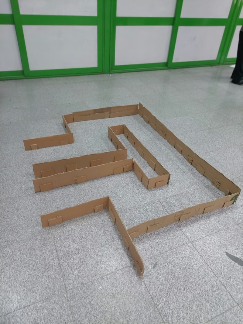
The Wall-Following Robot is an autonomous vehicle designed to navigate through a maze by maintaining a centered position between corridor walls. Beyond simple navigation, the robot tracks every turn it makes and transmits the final sequence to a PC via WiFi once it reaches the finish line. The system relies on a combination of proportional-derivative (PD) control for path smoothing and a robust finite state machine to handle complex environmental scenarios like junctions, dead ends, and open gaps.
Hardware Implementation
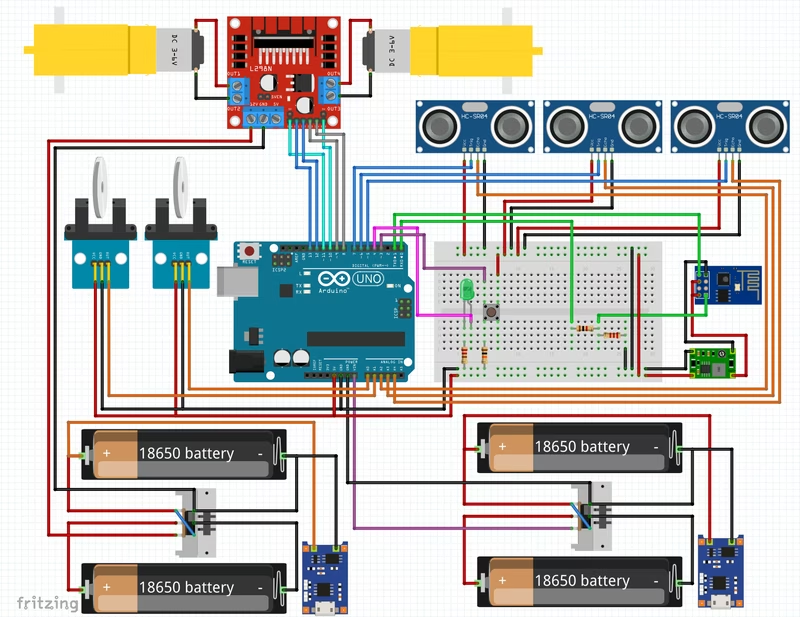
The robot’s brain is an Arduino Uno (ATmega328P). It interfaces with an L298N motor driver to control two geared DC motors equipped with 20-tick/rev wheel encoders. For environmental perception, it utilizes three HC-SR04 ultrasonic sensors mounted at the front, left, and right positions. Navigation accuracy is further enhanced by an MPU6050 IMU for measuring turn angles and an ESP-01 (ESP8266) module for wireless communication.
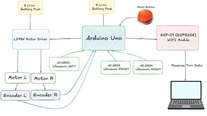
The hardware design is tightly integrated with the software; physical constants like the 6 cm wheel diameter and 12 cm wheelbase are used directly in the firmware’s calculation logic. The wiring is centralized in a single pin map file to ensure consistency between the physical breadboard layout and the code.
Software Architecture and Development
The project is developed using PlatformIO, allowing for efficient compilation and flashing to the Uno. Before deployment, users configure network credentials and server details within a configuration header. Once powered, the robot undergoes a brief arming period to allow the IMU to settle before beginning its run.
The firmware is modular, with each component handling a specific responsibility:
Low-Level Hardware API
To ensure predictable timing and a small binary footprint on the 32 KB ATmega328P, the HwApi module interacts directly with AVR registers. This bare-metal approach manages motor PWM via Timer0, a millisecond clock on Timer2, and ultrasonic echo timing on Timer1. Interrupts (INT0/INT1) are used for encoder feedback, minimizing the reliance on standard Arduino abstraction layers except for the MPU6050 DMP driver and Serial communication.
Sensor Fusion and Filtering
The robot operates on a fixed 25 ms control loop. During each tick, the ultrasonic sensors are pinged sequentially with an 8 ms buffer to prevent echo interference. To handle the inherent noise of HC-SR04 sensors, the system applies a median-of-3 filter and an exponential smoother. This ensures that the robot doesn’t react erratically to momentary glitches while still identifying genuine open spaces.
Steering and Navigation
The core of the movement logic is a PD controller that balances the distance between the left and right walls. If a wall disappears, the controller switches to tracking the remaining wall at a fixed distance. A slew-limited PWM output prevents motor snapping, while a speed-tapering mechanism slows the robot down as it approaches obstacles.
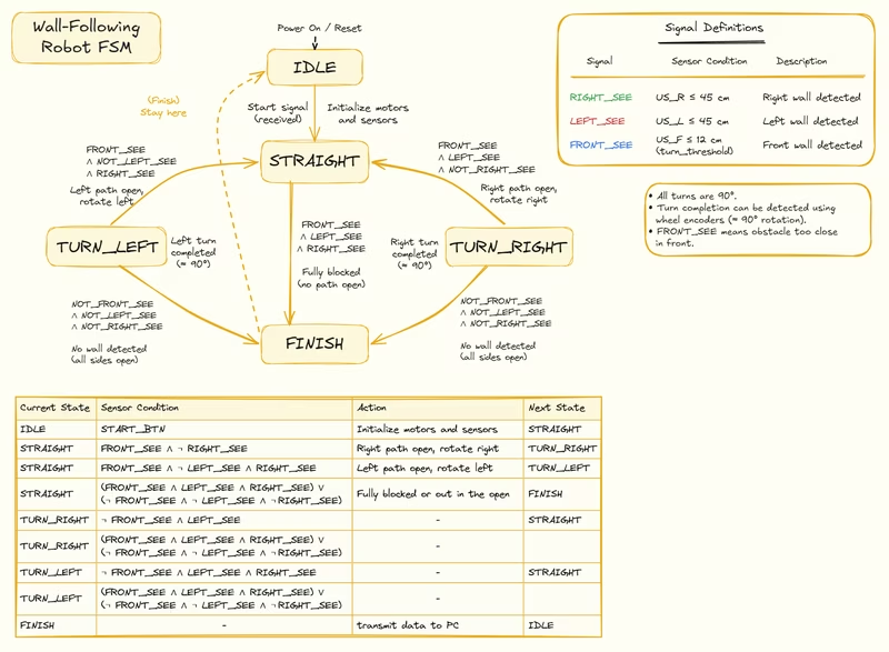
Complex navigation is managed by a finite state machine (FSM) and a TurnDetect module. The FSM identifies junctions and dead ends using debounced triggers and hysteresis to avoid oscillating on borderline sensor readings.
Turning and Reporting
Turns are primarily measured using the MPU6050’s Digital Motion Processor (DMP). To ensure reliability, the system features multiple fallbacks: if the DMP fails, it integrates raw gyroscope data; if the IMU fails entirely, it reverts to counting encoder ticks. This tiered approach ensures the robot can complete its sequence even under hardware degradation.
Upon reaching the finish, the robot uses the ESP-01 to join a WiFi network and send the recorded turn sequence (e.g., ‘L’, ‘R’, ‘U’) to a host PC via TCP. If the wireless connection is unavailable, the data is printed to the UART as a fallback.
Safety and Tuning
To prevent hardware damage, a stall watchdog monitors encoder ticks. If the motors are active but no movement is detected for 700 ms, the robot attempts a recovery maneuver or eventually shuts down. Behavioral parameters, including PD gains and distance thresholds, are managed via X-macros in the configuration file, enabling both static compilation and live tuning through a dedicated debug tool.
Related Projects
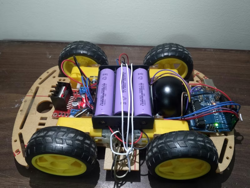
4WD Arduino Robot Car
This project implements a 4-wheel drive robotic platform controlled wirelessly via Bluetooth from a mobile device. It utilizes an Arduino microcontroller, an L298N motor driver, and an HC-05 module to enable real-time steering and PWM-based speed control. The system is designed as an open-source educational tool for learning hardware assembly, wireless communication, and embedded programming.
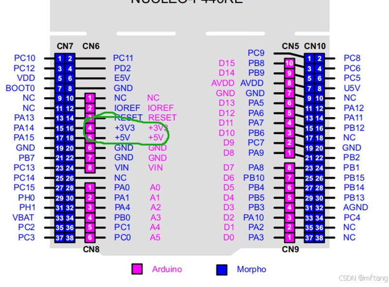
NoeticMaze
NoeticMaze is an embedded navigation and control system for the NUCLEO-F446RE development board, integrating Lidar, IMU, and motor control. Built on FreeRTOS, it implements advanced robotics algorithms including ICP-based localization, grid mapping, and A* path planning for autonomous differential-drive robots.
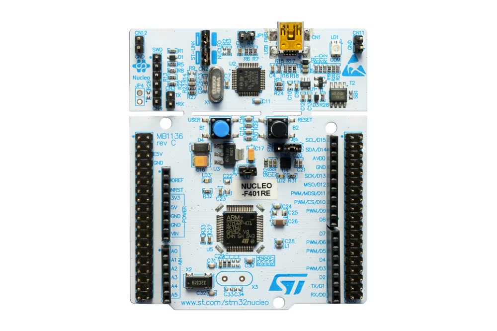
Autonomous Racing Robot (STM32 + ROS1)
A differential-drive autonomous robot utilizing an STM32F446RE for real-time motor control and ROS1 Noetic for mapping and navigation. The system employs a transparent Bluetooth communication link to perform laser-only SLAM via hector_slam on a remote host, optimizing performance for high-speed racing in static environments without the need for traditional odometry.
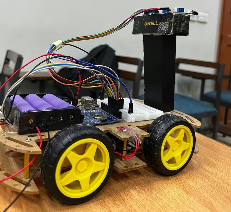
Human Following Robot
An autonomous mobile robot based on the Arduino Uno that uses a trio of infrared sensors to track and follow a person or object. The system integrates an L298N motor driver for motion control and features a dedicated Lithium-Ion charging circuit for portable operation.
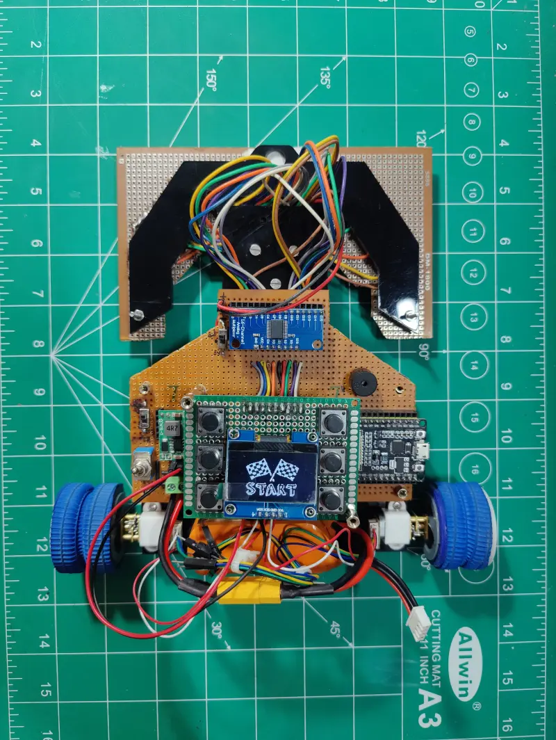
16 IR Array PID Line Follower Robot using ESP32
An advanced autonomous line follower robot utilizing a 16-channel IR sensor array and PID control. Powered by an ESP32 running MicroPython, the system features an OLED-based configuration menu for real-time tuning of control parameters and persistent storage of PID constants.
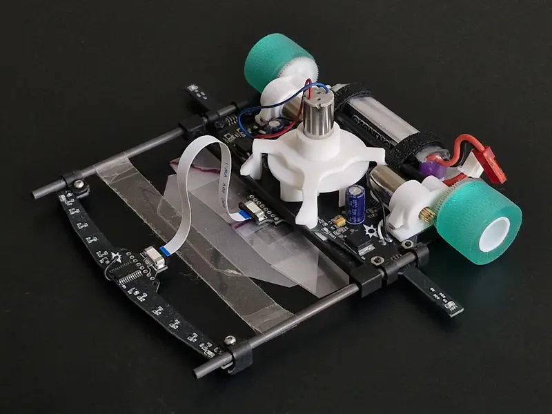
EVA-RT Robotracer
A high-performance robotracer featuring a centrifugal fan for increased downforce and specialized side sensors for curve detection. Built on the ATMEGA328P microcontroller, the project includes complete source code, PCB designs, and 3D models for a competitive line-following robot.