Temperature-Controlled Ventilation System for Indoor Environments
An STM32F103R6-based embedded system that provides automated and manual ventilation control based on real-time temperature monitoring. It utilizes an LM35 sensor, PWM for fan speed regulation, and an L298N H-bridge for direction control, with status updates displayed on an LCD1602. The project demonstrates peripheral integration using the STM32 HAL for ADC, timers, and external interrupts.
Maintaining a comfortable indoor environment requires a delicate balance between temperature sensing and mechanical response. This project implements a sophisticated ventilation control system built on the STM32F103R6 microcontroller, designed to manage airflow automatically or via manual user intervention. By integrating analog sensors, motor drivers, and visual feedback, it serves as a robust example of a closed-loop control system in the embedded space.
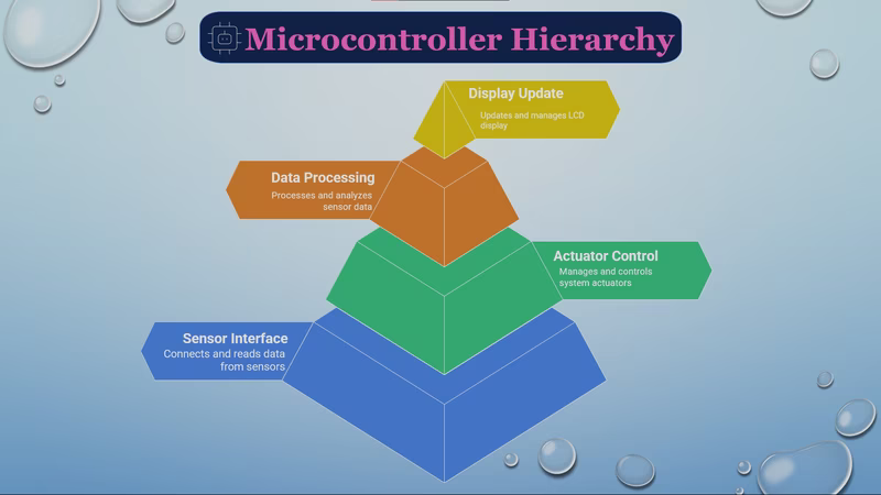
System Architecture and Logic
The heart of the system is the STM32F103R6, which processes data from an LM35 analog temperature sensor. The system logic is divided into two primary operating modes: Automatic and Manual.
In Automatic Mode, the system acts as an autonomous climate controller. It monitors the ambient temperature and responds based on predefined safety thresholds. If the temperature rises above 20°C, the system enters a “cooling mode,” spinning the fan counter-clockwise to facilitate airflow. Conversely, if the temperature drops below 10°C, it switches to a “heating mode,” reversing the fan direction to circulate warm air. When the temperature resides in the safe 10–20°C range, the fan stops to conserve energy. Visual and audible alerts—consisting of a red LED and a buzzer—trigger whenever the temperature exits the safe zone, while a green LED indicates stable conditions.
Manual Mode provides the user with granular control over the environment. Using five dedicated push buttons, a user can manually set the fan direction (Forward, Reverse, or Stop) and adjust the motor speed. The speed is regulated via Pulse Width Modulation (PWM), allowing for 10% incremental adjustments per button press, ranging from 0% to 100% duty cycle.
Hardware Integration
The project utilizes several key hardware components to achieve its goals:
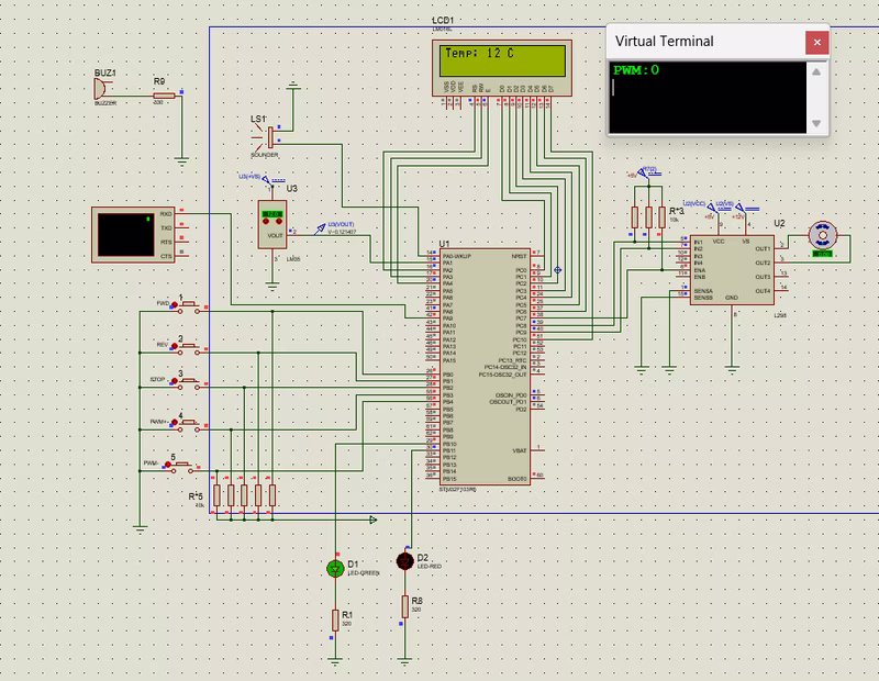
- LM35 Sensor: Provides a linear analog voltage output proportional to the Celsius temperature, which is read by the STM32’s ADC (PA1).
- L298N Dual H-Bridge: This motor driver is essential for controlling the DC fan’s direction and speed. It receives PWM signals from the MCU to modulate speed and uses GPIO pins (PC8, PC9) to toggle direction.
- LCD1602 Display: Real-time data, including current temperature and system status, is displayed on a 16x2 character LCD. Interestingly, this project uses a custom-written
lcd1602.hdriver, interacting directly with the STM32 HAL GPIO functions rather than relying on generic third-party libraries. - UART Communication: The system transmits the current PWM duty cycle over a serial interface (PA9), allowing for remote monitoring via a virtual terminal.
Software Implementation
The firmware is developed using the STM32 HAL (Hardware Abstraction Layer) within the Keil MDK-ARM environment. The configuration is managed through STM32CubeMX, which handles the initialization of the ADC for sensor reading, TIM3 for PWM generation, and EXTI (External Interrupts) for responsive button handling.
The control flow follows a standard embedded loop: the MCU polls the ADC for temperature changes, updates the LCD only when a significant change (≥0.5°C) is detected to prevent flickering, and then evaluates the motor logic based on the active mode. The use of external interrupts for the control buttons ensures that user inputs are processed immediately, providing a snappy interface even while the main loop handles display and sensor math.
Simulation and Testing
For developers looking to explore the project without physical hardware, the repository includes a comprehensive Proteus simulation setup. By loading the generated .hex file from the Keil build into the Proteus schematic, users can interact with the virtual buttons, observe the fan’s behavior, and see the real-time temperature updates on the virtual LCD. This makes it an excellent educational resource for understanding the interaction between firmware logic and electronic hardware.
Related Projects
Fully Automated Egg Incubator
An ATmega328P-based embedded system designed to automate the egg incubation process by regulating temperature, humidity, and rotation. It utilizes DHT11 and DS18B20 sensors for environmental monitoring and controls a stepper motor and relay-driven heating element to maintain optimal hatching conditions.
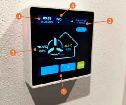
ComfoSense Touch: Zehnder ComfoAir Q350 MQTT Bridge & Controller
An ESP32-S3 based touch screen controller and MQTT bridge for Zehnder ComfoAir Q350 ventilation units. It replaces the ComfoSense hardware, providing a modern UI via LVGL and integrating with Home Assistant via CAN bus and MQTT.