Serial VGA Controller
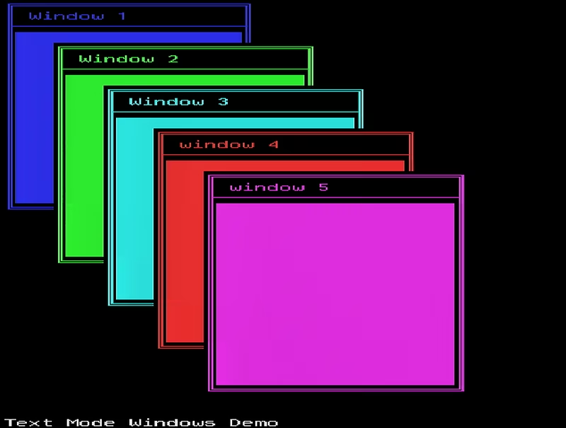
A high-performance VGA controller built around the 8-bit PIC18F47K42 microcontroller, capable of 360x480 resolution with 16 colors. It utilizes hardware peripherals like DMA, PWM, and SPI to generate signals with minimal CPU overhead, accepting ANSI-style escape sequences over a UART interface.
Pushing 8-Bit Hardware to the Limit
Generating a VGA signal is a demanding task for any microcontroller, requiring precise timing and high-speed data throughput. While modern 32-bit ARM chips or FPGAs handle this with ease, the Serial VGA Controller project takes a different path. It proves that with disciplined programming and clever peripheral management, even a resource-limited 8-bit PIC18F47K42 can produce a stable, 16-color video signal at an impressive 360x480 resolution.
At its core, the system functions as a serial terminal. It receives commands via UART, interprets ANSI-style escape sequences, and renders text or graphics to a VGA monitor. By offloading the synchronization and signal timing to the microcontroller’s internal hardware peripherals, the CPU remains free to handle command parsing and application logic.
Hardware-Assisted Synchronization
The VGA standard requires strict timing, traditionally based on a 25.175 MHz pixel clock. To accommodate the PIC18F47K42’s maximum external clock frequency, the project utilizes a 14.3182 MHz crystal—a frequency common in NTSC television equipment. By using the MCU’s internal 4x PLL, the system achieves an instruction clock of exactly 14.3182 MHz, matching the pixel clock.
Synchronization signals (HSYNC and VSYNC) are generated entirely in hardware. This deterministic approach ensures signal edges are jitter-free. The visible area is defined by the intersection of two PWM modules, which act as hardware gates to ensure pixel data is only transmitted during the active scanning period. The actual analog RGB output is produced by a minimal external circuit consisting of 74HC257 multiplexers and a simple R-2R resistor ladder DAC, mapping 4-bit color data to the standard 0.7V VGA range.
Architectural Design: Racing the Beam
The software follows a layered architecture designed to survive on just 14.3182 MIPS. Because the visible region of a VGA frame occupies over 90% of the CPU’s time, the system uses a “racing the beam” strategy. Time-critical video generation happens inside a high-priority Interrupt Service Routine (ISR) written in highly optimized Assembly.
For non-time-critical tasks, the project implements a “Reactor” module in the main loop. This module handles asynchronous events like UART buffer updates, DMA transfer notifications, and command processing. When data arrives via UART, the DMA engine stores it in a circular buffer without CPU intervention, allowing the interpreter to parse commands during the brief vertical blanking intervals.
Versatile Display Modes
The controller supports three distinct operating modes, each tailored for different visualization needs:
- Text Mode: Provides a 40x45 character grid. Each character is an 8x12 pixel glyph stored in FLASH memory. To achieve high performance, the system uses an 8-cycle pipeline in Assembly to fetch character data and color attributes simultaneously.
- Image Mode: Emulates the classic display characteristics of 1980s-era computers like the ZX Spectrum. It uses a compression technique where 1-bit bitmap data is combined with 8x8 “attribute” cells for color, allowing full-screen 360x480 images to fit within the limited memory of the PIC18.
- Plot Mode: A graphics-oriented mode with a resolution of 360x120. It supports individual pixel manipulation and geometric primitives like lines and circles. To maintain performance on a chip without a Floating Point Unit (FPU), the project utilizes Bresenham’s algorithms for all coordinate calculations.
Smart Command Interpretation
Communication with the controller is handled through a custom interpreter based on a Context-Free Grammar (CFG). By implementing a Finite State Machine (FSM) using the State Pattern, the system can parse complex escape sequences in real-time. This allows users to clear the screen, move the cursor, change colors, or draw shapes using standard terminal-style commands.
One of the most interesting technical hurdles solved in this project was “color bleeding.” Because instructions execute sequentially, selection signals originally reached the external multiplexers slightly before the color data. The developer solved this by introducing an intentional two-cycle “bubble” in the Assembly pipeline, ensuring that all signals arrive at the DAC perfectly synchronized for a crisp, flicker-free image.
Related Projects
KompressorKlock
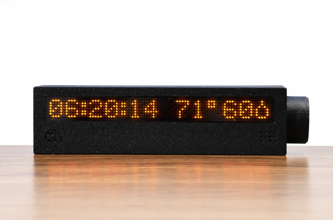
An embedded controller for the KompressorKlock project, built on the STM32G071G8Ux microcontroller. It manages user input via a rotary encoder and controls peripheral hardware using I2C and PWM signals. The system is developed using the STM32Cube G0 firmware package and standard HAL drivers.
picoAVE
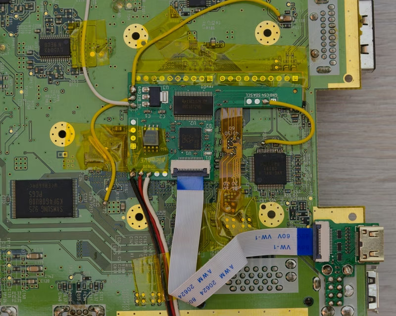
picoAVE is a hardware and software HDMI mod for the Nintendo Wii, powered by the Raspberry Pi RP2040 microcontroller. It utilizes a parallel video processing pipeline across both cores to deliver 480p output without information loss, leveraging the RP2040's PIO and DMA capabilities for TMDS encoding and audio serialization.
PICO TTL2VGA
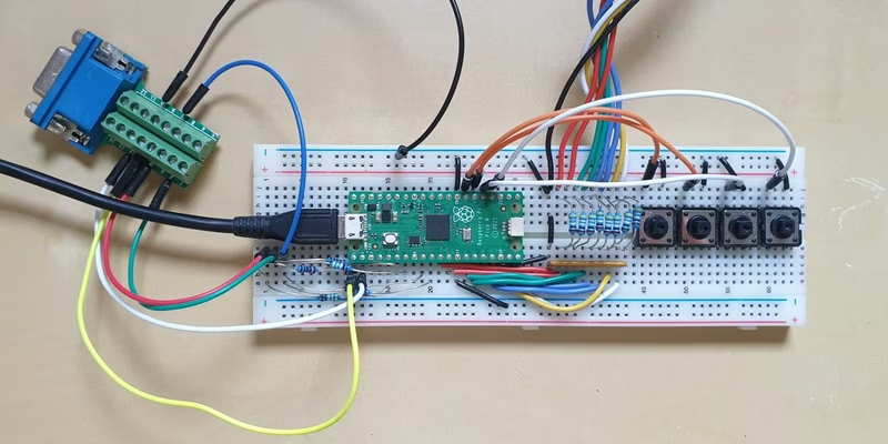
A Raspberry Pi Pico-based signal converter that translates legacy TTL video signals (MDA, CGA, and EGA) into modern VGA output at 720x400 @ 70Hz. It leverages the RP2040's PIO state machines and DMA for high-speed pixel capture and signal generation, supporting various legacy resolutions and frequencies.
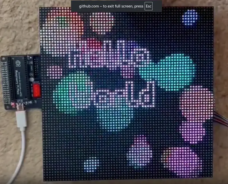
HUB75 DMA-Based Driver for Raspberry Pi Pico
A high-performance, DMA and PIO-based driver for HUB75 LED matrix panels targeting the RP2040 and RP2350 microcontrollers. It optimizes display rendering by offloading processing to hardware co-processors, enabling high refresh rates and advanced features like temporal dithering and software brightness control.