Project Shadow Flight
Project Shadow Flight is a 1U CubeSat designed for Earth Observation, built using the FreeRTOS framework on STM32 microcontrollers. It features a modular architecture including an On-Board Computer, a dedicated sensor board, and a VGA camera payload for capturing geo-referenced imagery. The system demonstrates the use of COTS components and the CCSDS Space Data Link Protocol for reliable satellite telemetry and control.
Project Shadow Flight is a homemade 1U CubeSat developed to demonstrate Earth Observation (EO) technology using accessible components. Built on the STM32 framework and powered by FreeRTOS, the project utilizes Commercial Off-The-Shelf (COTS) components to create a functional satellite bus capable of capturing geo-referenced low-resolution imagery from Low Earth Orbit (LEO).
Mission and Motivation
The project was born from a drive to explore space systems, mission software, and aerospace electronics. The primary mission objective is to operate in a sun-synchronous subrecurrent orbit, capturing images over specific areas based on ground station commands. These images are compressed and stored onboard before being transmitted back to Earth during a ground station pass. To optimize power and processing efficiency, image processing is deferred to the ground segment.
The satellite operates in two primary modes: Normal operation and Mission operation, both of which are configurable from the ground station.
System Architecture
The CubeSat follows a modular design consisting of several critical subsystems: the On-Board Computer (OBC), Communication and Data Handling (CD&H), Electrical Power Supply (EPS), Attitude Determination and Control (ADCS), and the Sensor and Payload systems. All PCBs utilize the PC/104 ISA bus standard, ensuring a stackable, rugged, and interoperable hardware configuration.
1. On-Board Computer (OBC)
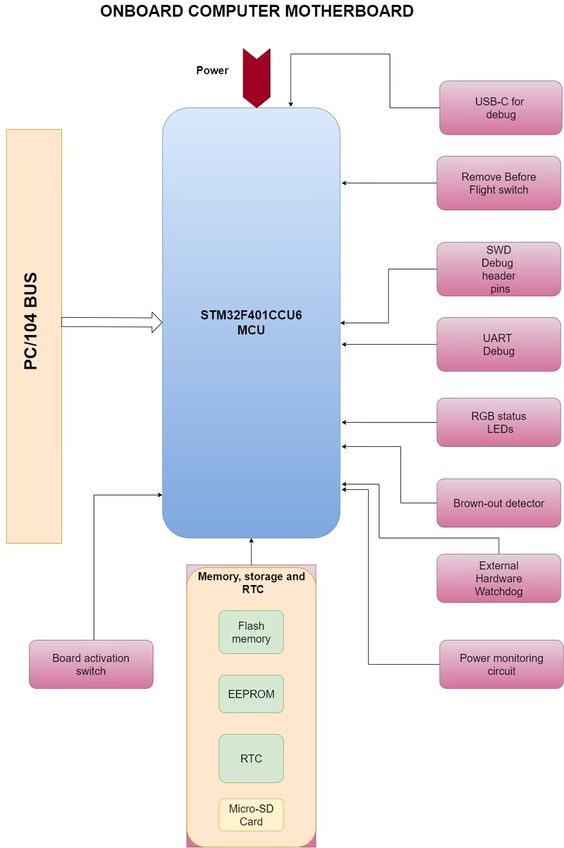
The OBC serves as the central hub, managing housekeeping tasks and coordinating communication between all subsystems. It is powered by an STM32F401CCU6 microcontroller and is designed to handle telemetry, command execution, and real-time control. Key features include non-volatile memory for mission-critical logs, a hardware watchdog timer for fault recovery, and brown-out detection to protect system integrity during power fluctuations.
The OBC also incorporates deployment and “Remove Before Flight” (RBF) switches, ensuring the satellite remains inactive until safely deployed from its carrier.
2. Sensor Board
The sensor board acts as the environmental monitoring unit for the satellite. It houses a suite of sensors including temperature, humidity, and barometric pressure sensors, along with sun sensors to determine sunlight intensity and direction. A dedicated low-power microcontroller manages data acquisition independently of the OBC, storing telemetry and image frames in local Flash memory.
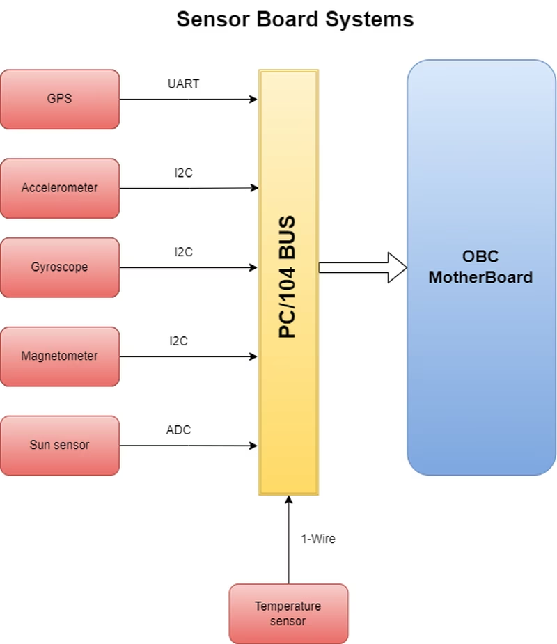
The board also includes a GPS module to provide real-time position, velocity, and timing data, which is essential for orbital tracking and geo-referencing payload data.
Attitude Determination and Control (ADCS)
The ADCS receives attitude data from the sensor suite and processes it in real-time to control the satellite’s orientation. This system is primarily implemented in software, where algorithms interpret sensor inputs to drive actuators that maintain the desired pointing accuracy for the Earth Observation mission.
Electrical Power System (EPS)
The EPS manages energy generation, conversion, storage, and distribution. It is responsible for regulating power from the solar panels and managing the battery charge cycles. The design process involves a rigorous power budget analysis to ensure the CubeSat can sustain operations throughout its mission profile, from initial deployment to active imaging sessions.
Payload and Mission Design
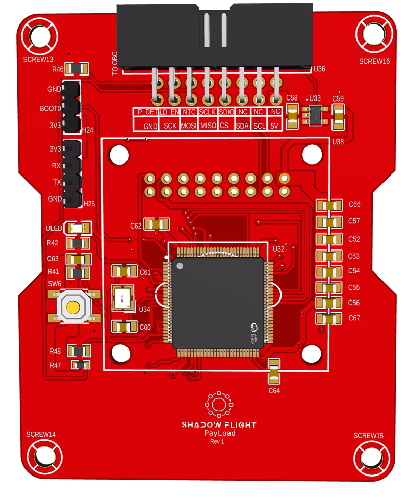
The primary payload is a color VGA camera module (OV7670) designed for Earth Observation. This system is implemented as a daughter-board mounted to the OBC. It uses an STM32F407VGT6 MCU featuring a Digital Camera Interface (DCMI) to handle the 8-bit parallel video data bus.
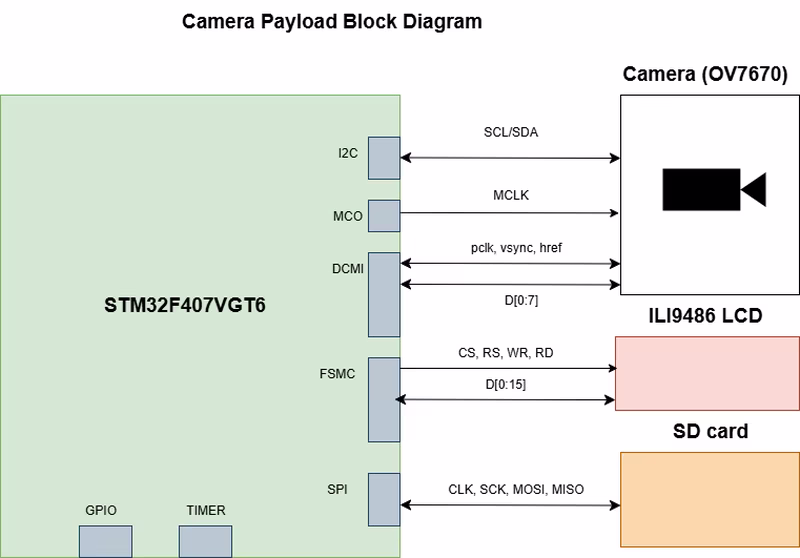
The payload MCU supports both continuous and snapshot modes, allowing for flexible imaging operations. While an LCD interface is included on the payload PCB for ground testing, the flight version focuses on lightweight image compression and DMA-based data handling to meet the downlink constraints of less than 100 kbps.
Communication Protocol
For data transmission, Project Shadow Flight implements a modified version of the CCSDS Telemetry (TM) Space Data Link Protocol. This standardized protocol ensures that telemetry and science data are packaged into Transfer Frames that are compatible with professional ground station systems.
The protocol implementation covers the Primary Header (including Spacecraft ID and Frame Counts), optional Secondary Headers for mission-specific timestamps, and the Frame Error Control Field (FECF) using CRC-16 for error detection. When no telemetry is available, the system transmits Only Idle Data (OID) frames to maintain link synchronization.
Related Projects
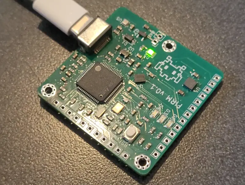
Filtered Inertial Rotation Module (FIRM)
FIRM is a high-powered rocketry flight computer firmware designed for accurate attitude and position tracking. Built for the STM32F405 microcontroller, it utilizes FreeRTOS and advanced Kalman filtering to process data from an array of inertial and environmental sensors.