PD240W
PD240W is an adjustable power supply designed for motor drives, leveraging USB-C Power Delivery 3.1 to deliver up to 240W at 48V 5A. Built on the Raspberry Pi Pico (RP2040) platform, it features a custom C++17 firmware stack for high-voltage negotiation, hardware-level safety monitoring via the INA228 power monitor, and a rich LCD user interface.
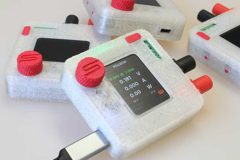
PD240W is an adjustable power supply specifically designed for motor drives, leveraging the latest USB-C Power Delivery (USB-PD) standards to provide significant power output in a compact form factor. The device is capable of negotiating up to 240W at 48V and 5A, making it a versatile tool for high-power electronics projects. It is designed to be compatible with USB-PD 3.1 and above, running on the Raspberry Pi Pico’s RP2040 microcontroller.
High-Power Features and Capabilities
The system’s core functionality revolves around its ability to negotiate various USB-PD profiles, including Fixed, PPS (Programmable Power Supply, 5-21V), and AVS (Adjustable Voltage Supply, 15-48V EPR). Safety is a primary focus, with hardware-level overcurrent protection managed by an INA228 power monitor and a dedicated overcurrent Interrupt Service Routine (ISR). The current limit is user-adjustable from 50mA to 5A in 50mA steps.
Beyond power delivery, the device includes several sophisticated firmware features:
- Auto PPS Tuning: A closed-loop voltage correction system to ensure the charger output matches the requested voltage accurately.
- Energy Monitoring: Real-time tracking of mAh delivered since boot using the INA228’s charge accumulator.
- Safety Interlocks: Overtemperature monitoring via NTC and the power monitor, alongside configurable startup behaviors like auto-output on boot.
- User Interface: A 240x320 ST7789 LCD display featuring anti-aliased fonts and a navigation system inspired by Prusa 3D printers.
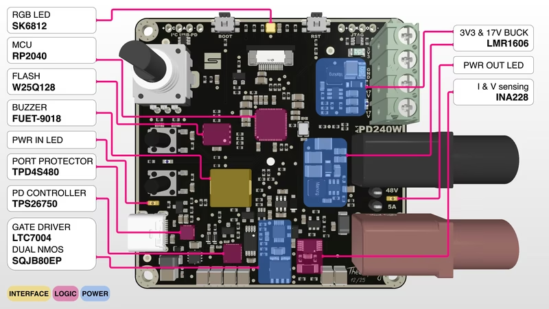
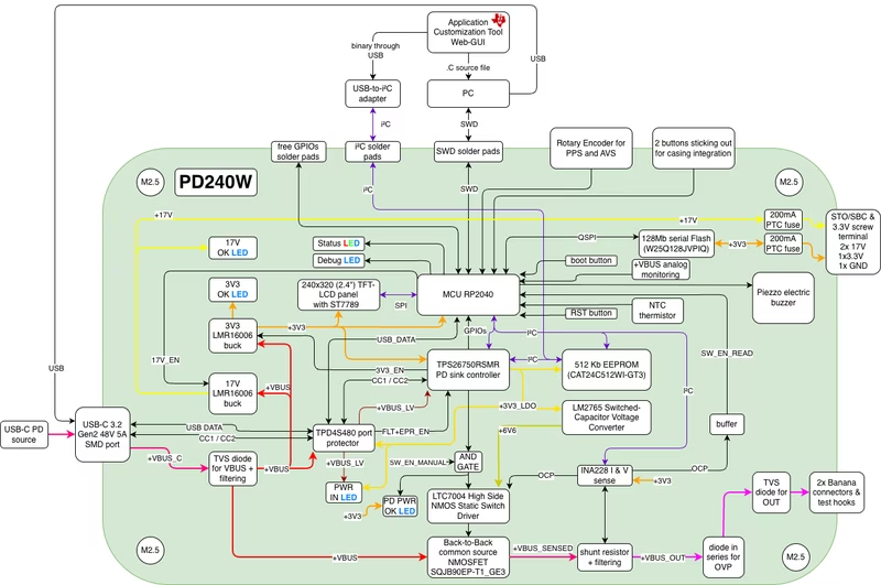
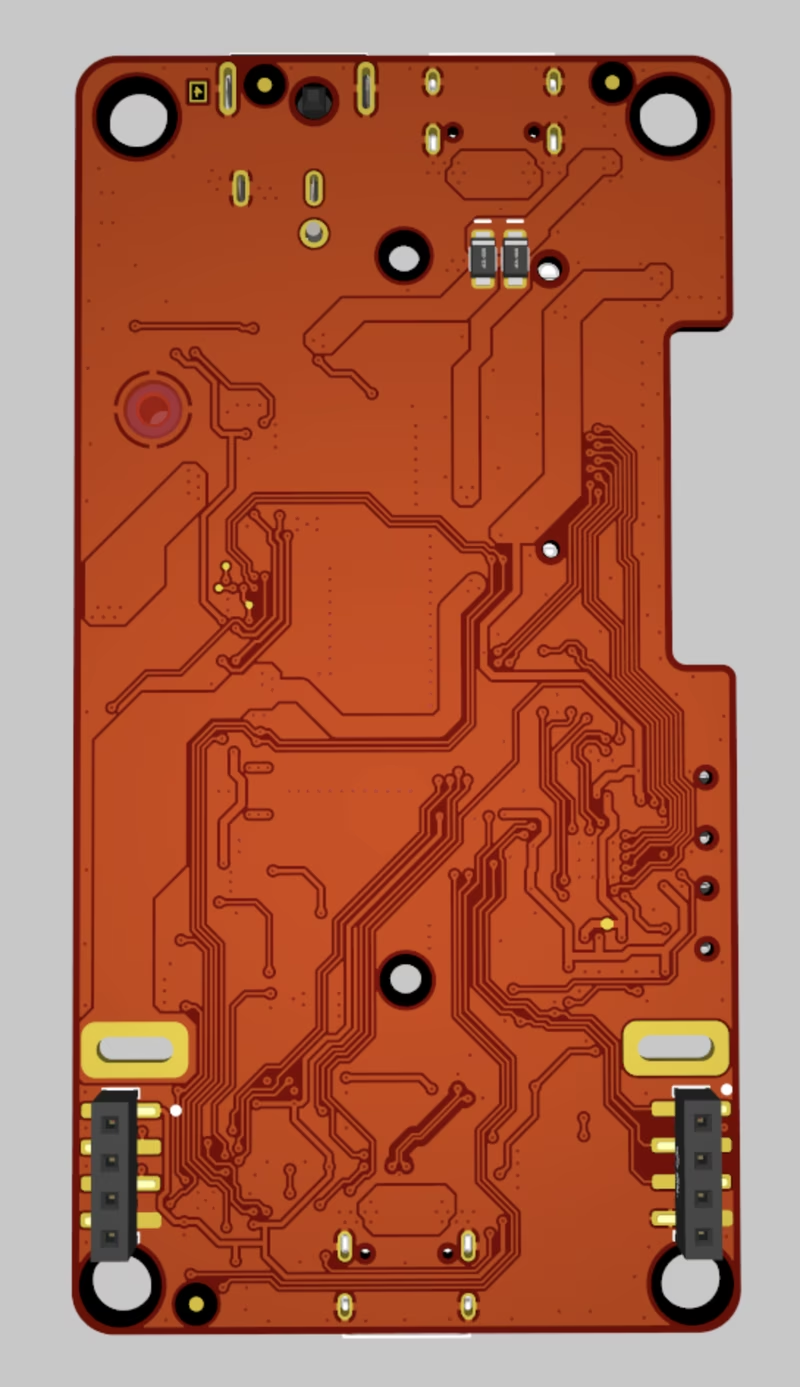
Hardware Architecture
The hardware is built around a multi-layered design incorporating specialized controllers for power and communication. The PCB layout integrates the RP2040 MCU, a TPS26750 USB-PD controller for contract negotiation, and an INA228 for high-precision current and voltage sensing.
As shown in the system diagram, the RP2040 communicates with the PD controller and power monitor via I2C, while the display is driven via SPI. The device also includes an optional 17V buck output, designed to provide a mock STO/SBC voltage for motor drive safety circuits.
Getting Started and Configuration
Operating the PD240W requires flashing the RP2040 with the provided firmware via the standard BOOTSEL method. However, a critical step for initial setup is the TPS26750 EEPROM configuration. Before the device can perform full PD negotiation, the user must execute the EEPROM Flash workflow found in the system’s settings menu. Until this is completed, the board will only operate in standard 5V non-PD modes.
For those building from source, the project utilizes the Pico SDK 2.2.0 and requires a standard ARM GCC toolchain with CMake and Ninja. The build process generates a standard UF2 binary for easy deployment.
Interface and Controls
The user interaction is handled through a rotary encoder and two physical buttons. The encoder allows for menu navigation and value adjustments (utilizing velocity tracking for faster scrolling), while the buttons toggle the main load switch and the auxiliary 17V buck output.
The menu structure is organized into a hierarchical flow, allowing users to select voltage profiles (PDOs), set current limits, and access deep configuration settings such as LCD brightness, auto-dim timeouts, and startup melodies.
Firmware Structure
The firmware is written in C++17 and follows a modular architecture designed for the RP2040. It avoids a traditional RTOS in favor of a non-blocking main event loop and a centralized GPIO interrupt router.
- Drivers: Low-level abstractions for the ST7789 display, INA228 power monitor, and TPS26750 controller. It includes custom PIO state machines for driving RGB LEDs and PWM-based melody playback.
- Logic Layer: This contains the state machines for the UI flow, safety monitoring, and PD contract management. It handles the complexities of PPS keep-alive signals and auto-tuning.
- UI Manager: Manages all screen rendering, utilizing an anti-aliased font engine to ensure high-quality text on the small display.
- Settings: A flash persistence layer with CRC32 validation ensures that user preferences and safety limits are saved across power cycles.
Related Projects
Web3 Pi UPS
An open-source DC uninterruptible power supply designed specifically for the Raspberry Pi 5, featuring triple-input power paths and smart battery management. It utilizes a dual-MCU architecture with a CH32X035 for power delivery and an RP2040 for the user interface, while supporting remote monitoring via FreeRTOS and the lwIP stack.
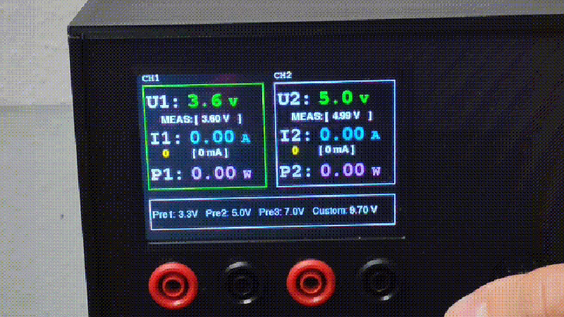
ESP32 Lab Power Supply
A DIY dual-channel laboratory power supply controlled by an ESP32, featuring a 3.5-inch TFT display and rotary encoder interface. It utilizes stepper motors for precise physical adjustment of voltage regulators and implements a closed-loop feedback system using INA219 sensors for accurate voltage and current monitoring.
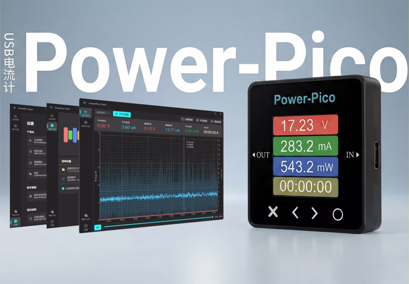
Power-Pico
Power-Pico is a high-precision, low-power analysis tool and USB ammeter designed for embedded developers. It features an STM32F411 MCU running FreeRTOS and the LVGL graphics library, enabling real-time waveform display and current measurement from 1μA to 5A through multi-range automatic switching.
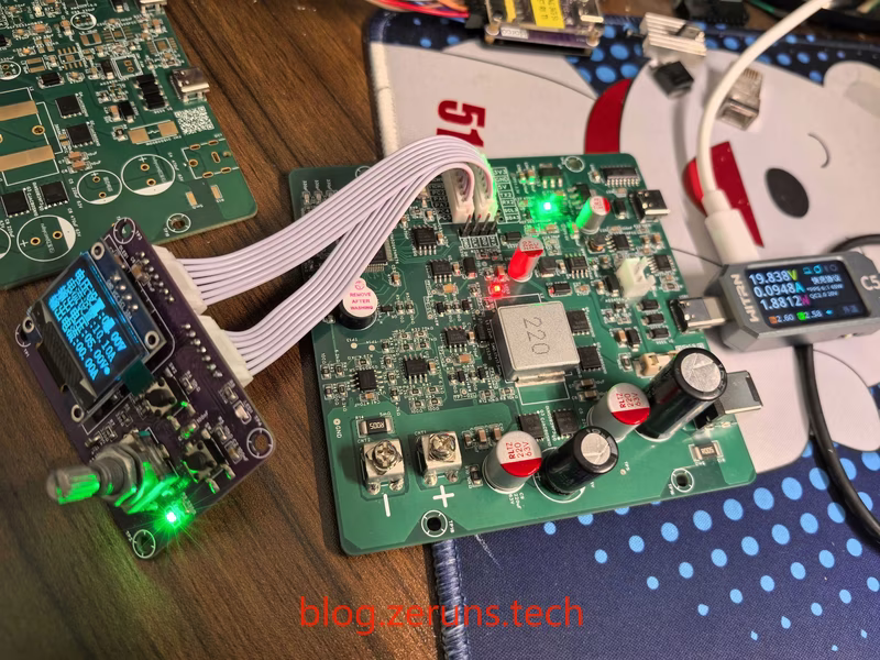
STM32 Synchronous Rectification Buck-Boost Digital Power Supply
A high-performance digital power supply based on the STM32G474, featuring a four-switch Buck-Boost architecture for wide-range voltage regulation. It supports up to 450W output (48V 10A) with dual DC and USB-C PD inputs, utilizing high-resolution PWM and PID control for precise power management.
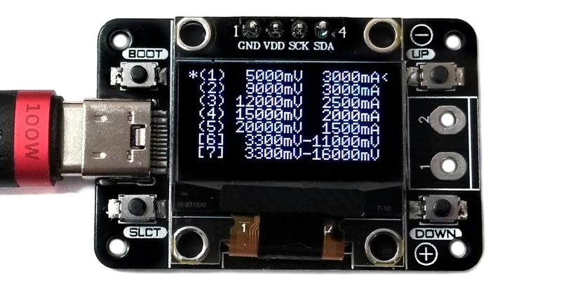
USB PD Tester
A monitoring and triggering device for USB Power Delivery built around the CH32X035 RISC-V microcontroller. It identifies power supply capabilities via PDOs, displays them on an OLED screen, and allows users to select specific voltages for output via a screw terminal. The project leverages the integrated USB PD PHY of the CH32X035 for a compact and low-cost hardware implementation.
USB PD Adapter
A compact variable power supply that utilizes the PPS feature of USB Type-C PD supplies to provide adjustable output voltages and currents. It is powered by the CH32X035 RISC-V microcontroller and includes an INA219 sensor for real-time power monitoring and an OLED display.