ESP32 Lab Power Supply
A DIY dual-channel laboratory power supply controlled by an ESP32, featuring a 3.5-inch TFT display and rotary encoder interface. It utilizes stepper motors for precise physical adjustment of voltage regulators and implements a closed-loop feedback system using INA219 sensors for accurate voltage and current monitoring.
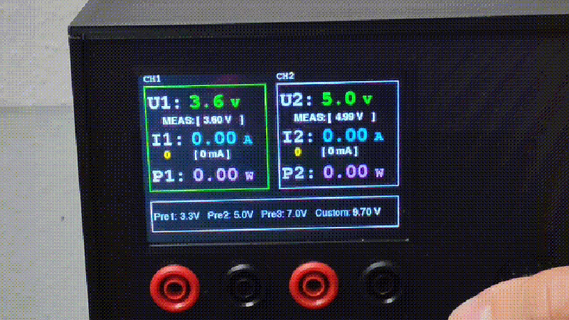
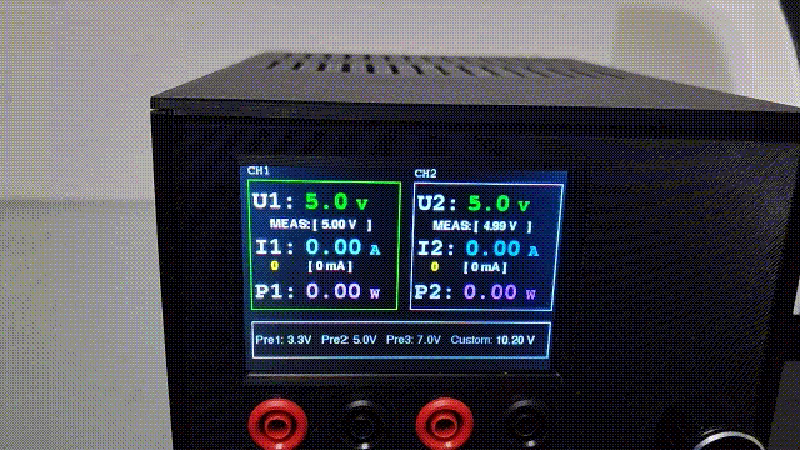
The ESP32 Lab Power Supply is a DIY laboratory-grade power solution designed for versatility and precision. Built around the ESP32 DevKit, this project provides a dual-channel output with integrated voltage and current control, managed through a modern graphical interface on a 3.5” TFT display.

Key Features
The system is designed for ease of use and flexibility in a lab environment. Key capabilities include:
- Dual Output Control: Independent management of voltage and current across two channels.
- Intuitive Interface: A rotary encoder allows for tactile navigation and adjustment, while the TFT_eSPI library drives a responsive display.
- Preset Modes: Quick-access buttons for common voltages such as 3.3V, 5V, and 7V, alongside fully customizable user modes.
- Modern Maintenance: Support for Over-the-Air (OTA) firmware updates ensures the system can be improved without physical disassembly.
Hardware Configuration
The project integrates several specialized modules to achieve high-precision control. At its core, an ESP32 DevKit coordinates the interaction between user input and hardware regulation. The display is an ILI9488 3.5” TFT, providing ample screen real estate for monitoring metrics.
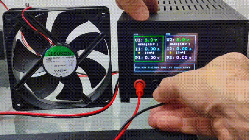
Unique to this design is the use of SM-28BYJ-48-5V stepper motors paired with ULN2003 drivers. These motors are used to physically adjust the regulation hardware, providing a bridge between digital logic and analog power delivery. Power monitoring is handled by two INA219 current sensors, while the main power regulation is managed by LM2596S-PSUM and SCT2650-STP-DWN modules. Thermal management is provided by a 40x40 12V fan.
Setup and Pin Configuration
To initialize the system, the ESP32 core must be installed in the Arduino IDE alongside the TFT_eSPI, Adafruit INA219, and ArduinoOTA libraries. A critical step in the setup process involves modifying the User_Setup.h file within the TFT_eSPI library to match the specific pin assignments of the hardware.
| Pin | Function | Description |
|---|---|---|
| GPIO 5 | Motor M1_IN1 | Motor driver input 1 for channel 1 |
| GPIO 19 | Motor M1_IN2 | Motor driver input 1 for channel 2 |
| GPIO 27 | Motor M1_IN3 | Motor driver input 1 for channel 3 |
| GPIO 33 | Motor M1_IN4 | Motor driver input 1 for channel 4 |
| GPIO 32 | Motor M2_IN1 | Motor driver input 2 for channel 1 |
| GPIO 25 | Motor M2_IN2 | Motor driver input 2 for channel 2 |
| GPIO 26 | Motor M2_IN3 | Motor driver input 2 for channel 3 |
| GPIO 14 | Motor M2_IN4 | Motor driver input 2 for channel 4 |
| GPIO 12 | Display LED | TFT display LED pin |
| GPIO 15 | Display CS | TFT display chip select |
| GPIO 2 | Display DC | TFT display data/command |
| GPIO 4 | Display RST | TFT display reset |
| GPIO 18 | Display CLK | TFT display clock (SPI SCK) |
| GPIO 23 | Display MOSI | TFT display data line (SPI MOSI) |
| GPIO 34 | Rotary Encoder A | Rotary encoder signal A |
| GPIO 35 | Rotary Encoder B | Rotary encoder signal B |
| GPIO 21 | INA219 SDA | INA219 sensor data line (I2C) |
| GPIO 22 | INA219 SCL | INA219 sensor clock line (I2C) |
Hybrid Control and Closed-Loop Feedback
This power supply utilizes a hybrid control architecture that merges digital precision with analog feedback. Unlike simpler systems that rely on open-loop setpoints (where the controller sends a signal and assumes the output is correct), this project implements a closed-loop mechanism.
In this closed-loop system, the output voltage and current are continuously measured in real-time. These actual values are fed back into the ESP32 controller, which then calculates the necessary adjustments to the stepper motors. This ensures that the output remains stable and precise even as load conditions change or components heat up. For users seeking even smoother voltage fine-tuning, the addition of an optional 1 kΩ / 0.6 W metal film bleeder resistor is recommended to help discharge capacitors during downward voltage adjustments.
Related Projects
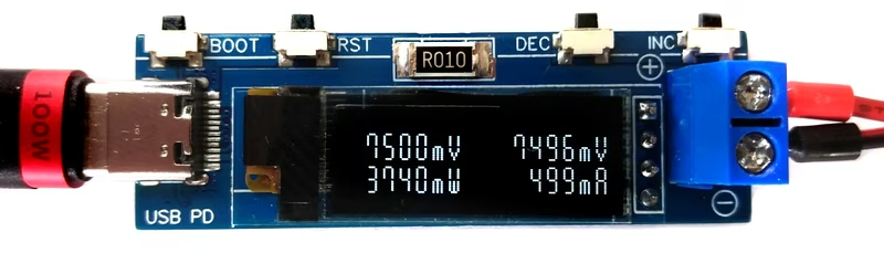
USB PD Adapter
A compact variable power supply that utilizes the PPS feature of USB Type-C PD supplies to provide adjustable output voltages and currents. It is powered by the CH32X035 RISC-V microcontroller and includes an INA219 sensor for real-time power monitoring and an OLED display.
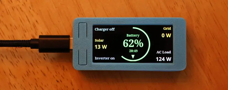
ESP32 Remote for Victron
An open-source monitoring and control solution for Victron Multiplus II systems using the LilyGo T-Display S3 AMOLED. Built on the ESP32 platform, it provides real-time data on solar power, grid status, and battery health while allowing users to toggle charger and inverter functions.
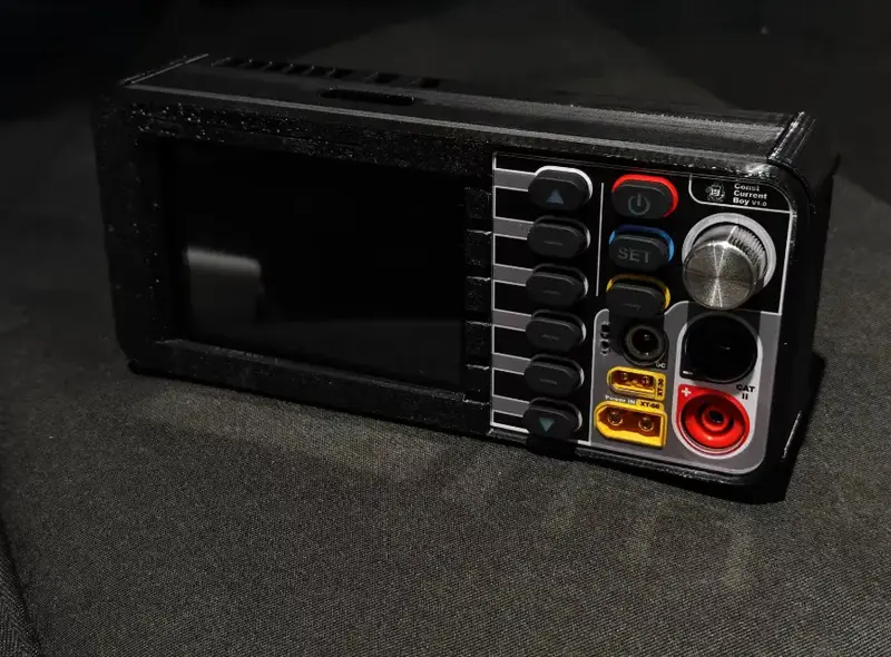
ELEVOURER: Portable Intelligent Electronic Load
An ESP32-S3 based portable intelligent electronic load featuring high-precision control and a rich graphical interface. It utilizes FreeRTOS for multi-tasking and integrates PID and Model Predictive Control (MPC) algorithms with Kalman filtering for accurate current regulation. The system supports Constant Current (CC), Constant Power (CP), and Constant Resistance (CR) modes with real-time monitoring via LVGL.
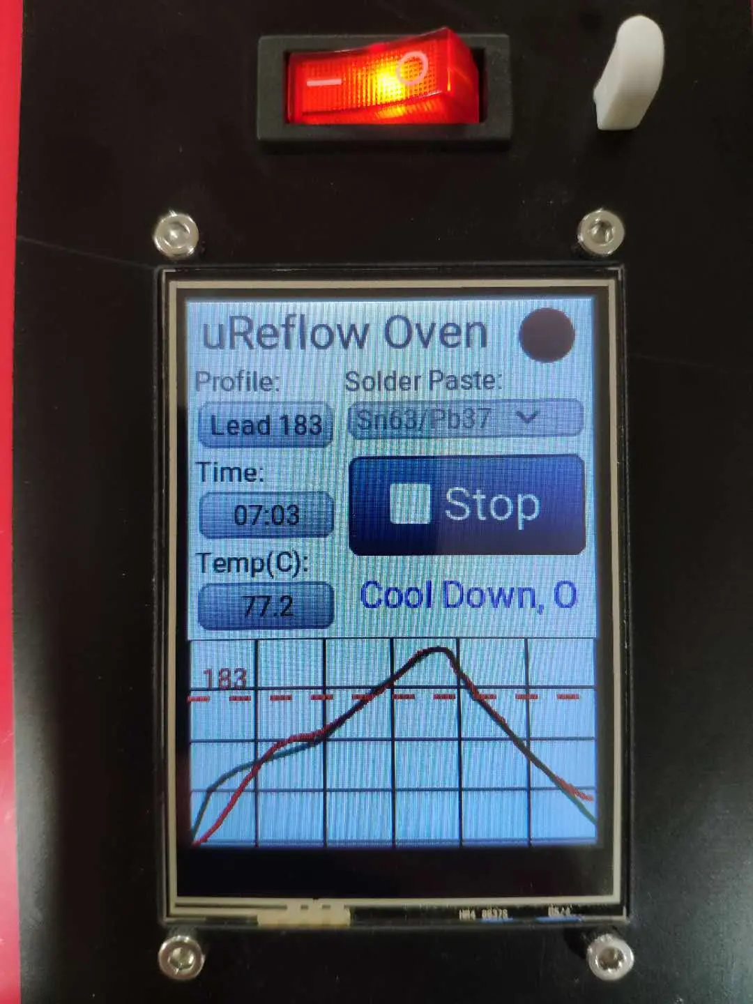
μReflow Oven with MicroPython & LVGL
A PID-controlled reflow oven controller built for the ESP32 using MicroPython and the LVGL graphics library. It features a touch-screen interface for selecting solder profiles, real-time temperature monitoring via thermocouple amplifiers, and remote configuration via FTP.
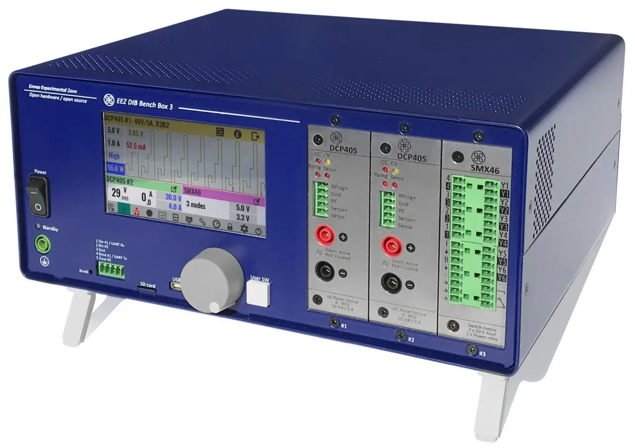
EEZ Bench Box 3 (BB3) Modular Power Supply Platform
An open-source modular Test and Measurement platform centered around an STM32F769 ARM Cortex-M7 MCU. It provides a complete hardware and software framework for modular power supplies and data acquisition, supporting visual programming via EEZ Flow, SCPI commands, and MicroPython scripting.