OpenScope 2C53T
An open-source firmware replacement for the FNIRSI 2C53T 3-in-1 handheld instrument. Built on FreeRTOS and targeting the Artery AT32F403A MCU, it provides a complete rewrite of the oscilloscope, multimeter, and signal generator functions.
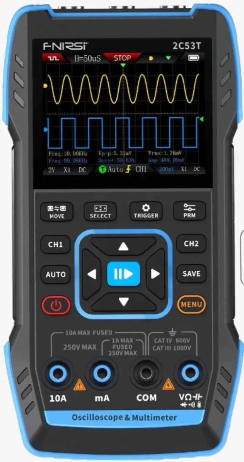
The FNIRSI 2C53T is a popular, budget-friendly handheld device that combines an oscilloscope, multimeter, and signal generator into a single unit. While the hardware is impressive for its price point, the stock firmware is often cited as a limiting factor. OpenScope 2C53T is a clean-room firmware rewrite designed to unlock the full potential of this hardware through extensive reverse engineering and modern embedded practices.
Hardware and Architecture
At the heart of the device is the Artery AT32F403A, a high-performance ARM Cortex-M4F microcontroller clocked at 240MHz. Interestingly, the MCU markings on the physical hardware are sanded off; the project identified the chip through register probing, discovering it is register-compatible with GD32 and STM32 series at the GPIO level. The system architecture is split between this MCU and a Gowin GW1N-UV2 FPGA, which handles the high-speed 250MS/s ADC sampling.
The firmware leverages FreeRTOS to manage various concurrent tasks. A high-priority task scans the 15-button matrix at 500Hz to ensure responsive input, while other tasks handle the ST7789V 320x240 display via a 16-bit parallel bus (EXMC), battery management, and watchdog monitoring. This multi-tasking approach allows for a fluid UI with four navigable modes and multiple color themes, including high-contrast and night-red options.
Reverse Engineering Success
One of the most impressive aspects of the project is its documentation of the original hardware. Using Ghidra to analyze the stock binary, the developers mapped over 300 functions and traced every hardware pin. This effort led to the complete documentation of the FPGA protocol, including the 115,638-byte calibration table upload sequence required at boot.
This deep understanding of the hardware enables features that go beyond basic signal display. The firmware includes an FFT spectrum analyzer with 4096 points and five window functions, protocol decoders for UART, SPI, I2C, CAN, and K-Line, and a Bode plot engine for frequency response analysis.
Development and Extensibility
For developers, the project offers a sophisticated toolchain and emulation environment. It supports building for real hardware using the GNU Arm Embedded Toolchain or running in an emulator. The emulator utilizes Renode and an SDL3-based LCD viewer, allowing UI and logic development to proceed without needing the physical device connected.
The firmware also features a custom USB HID bootloader. While the initial installation requires opening the case to enter the AT32’s ROM DFU mode—necessary for configuring the 224KB SRAM mode via option bytes—all subsequent updates can be performed over USB-C with the case closed. This “In-Application Programming” (IAP) approach makes the device much more accessible for regular firmware updates and community-driven improvements.
Current Capabilities
Currently, the firmware provides a fully functional UI, multimeter data flow, and signal generator controls. The system supports variable-width bitmap fonts, soft power management with a countdown shutdown, and screenshot capture to BMP. While the critical path for the oscilloscope functionality (FPGA SPI3 data acquisition) is the primary focus of active development, the framework for measurements, math channels, and persistence display is already implemented and unit-tested.