M5StickCPlus2 AMG8833 Thermal Camera
A portable thermal camera application for the M5StickCPlus2 using the AMG8833 infrared sensor. It features real-time thermal imaging with bilinear interpolation, auto-ranging color palettes, and battery monitoring. The project is built using the Arduino framework and the M5Unified library for ESP32-based hardware.
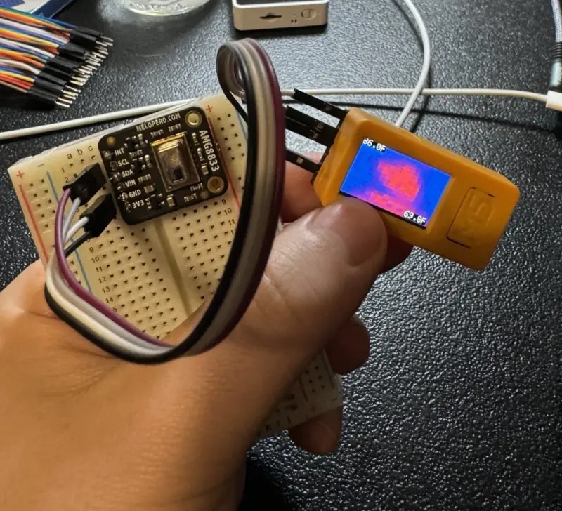
Portable Thermal Imaging with M5StickCPlus2
The M5StickCPlus2 AMG8833 Thermal Camera project transforms a compact ESP32-S3 development kit into a functional handheld thermal imager. By interfacing with the Panasonic AMG8833 Grid-EYE sensor, the system captures an 8x8 array of infrared temperature points and processes them for real-time visualization on the device’s built-in LCD.
Technical Implementation and Interpolation
While the AMG8833 sensor provides a native resolution of only 64 pixels (8x8), this project employs bilinear interpolation to upscale the thermal data to a 16x16 grid. This software-based enhancement smooths the transitions between temperature points, resulting in a more readable and visually appealing thermal map.
The core logic utilizes the Adafruit_AMG88xx library for sensor communication and the M5StickCPlus2 (M5Unified) library for display and power management. To ensure a high refresh rate, the I2C bus is configured to run at 400kHz on GPIO pins 25 (SDA) and 26 (SCL).
Key Features
- Auto-Ranging Colors: The application dynamically maps the detected temperature range (minimum to maximum) to a color gradient, ensuring that thermal contrasts are visible regardless of the absolute temperature of the environment.
- Real-Time Statistics: The display provides instant feedback on the highest and lowest temperatures detected in the frame, converted to Fahrenheit for user convenience.
- Power Management: Leveraging the M5StickCPlus2’s power circuitry, the project includes a battery percentage indicator and a dedicated power-off sequence triggered by the main front button (Button A), complete with an audible beep.
- Hardware Integration: The repository includes an STL file for a 3D-printable case, allowing the sensor and the M5StickCPlus2 to be securely mounted as a single unit.
Software Architecture
The firmware is structured around a standard Arduino loop that performs four primary tasks: reading the raw pixel data from the sensor, calculating the min/max temperature bounds, interpolating the data for the display grid, and updating the LCD.
// Example of the interpolation logic used to smooth the thermal image
void interpolateImage(float input[GRID_SIZE][GRID_SIZE], float output[INTERPOLATED_SIZE][INTERPOLATED_SIZE]) {
    for (int i = 0; i < INTERPOLATED_SIZE; i++) {
        float rowRatio = (float)(i) / (INTERPOLATED_SIZE - 1) * (GRID_SIZE - 1);
        int iLow = floor(rowRatio);
        int iHigh = ceil(rowRatio);
        float rowFrac = rowRatio - iLow;

        for (int j = 0; j < INTERPOLATED_SIZE; j++) {
            float colRatio = (float)(j) / (INTERPOLATED_SIZE - 1) * (GRID_SIZE - 1);
            int jLow = floor(colRatio);
            int jHigh = ceil(colRatio);
            float colFrac = colRatio - jLow;

            float top = interpolate(input[iLow][jLow], input[iLow][jHigh], colFrac);
            float bottom = interpolate(input[iHigh][jLow], input[iHigh][jHigh], colFrac);

            output[i][j] = interpolate(top, bottom, rowFrac);
        }
    }
}
To optimize performance, the display logic only updates specific pixels on the LCD if the temperature change exceeds a 0.5-degree threshold. This reduces the SPI overhead and prevents unnecessary flickering, allowing for a smoother user experience on the ESP32-S3 platform.