E-ink Meeting Room Schedule Display
A wireless e-ink device based on the ESP32-powered Soldered Inkplate 6 platform that displays meeting room schedules. It utilizes the Roombelt backend for data and features a secondary digital photo frame mode that reads images from a microSD card.
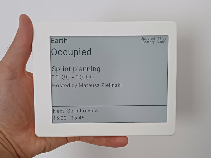
Creating a wireless e-ink device provides an elegant solution for displaying schedules for meeting rooms or home offices. This project leverages high-visibility e-paper technology to create a low-power display that remains readable in various lighting conditions without the glare of traditional screens.
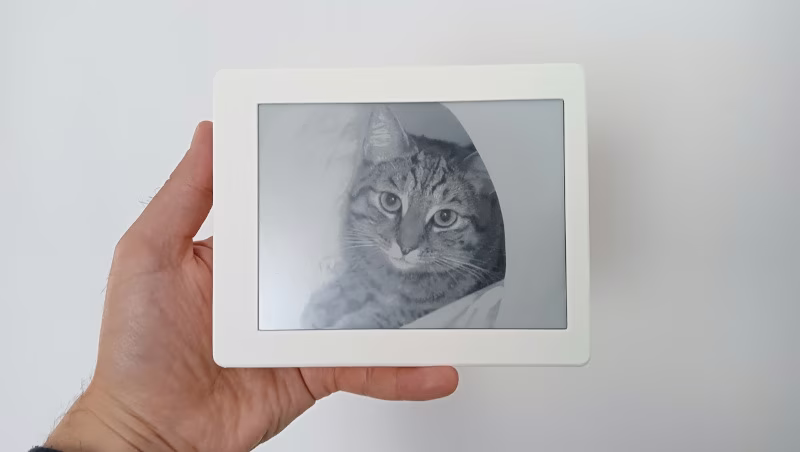
Beyond its primary function as a schedule tracker, the device is designed to be versatile. After office hours, it can automatically transition into a digital photo frame. In this mode, it displays images stored on a microSD card, making it an aesthetic addition to a home office environment when not in active use for meetings.
Hardware Platform
The system is built around the Soldered Inkplate 6, a powerful e-paper board powered by an ESP32 microcontroller. This board is specifically chosen for its integrated Wi-Fi capabilities and ease of use with the Arduino framework. To ensure portability and a clean aesthetic, the device is powered by a 3.7V Li-ion battery (3000mAh or greater) and housed in a custom 3D-printed case consisting of a front frame and a back cover.
For data connectivity and scheduling, the device uses Roombelt as its backend service. This integration allows the display to fetch real-time calendar information and update the e-ink screen accordingly.
Firmware and Development
The firmware is developed using PlatformIO within the Visual Studio Code environment. It utilizes the Arduino framework for ESP32, specifically targeting the esp32dev board configuration. The build process incorporates the Inkplate-Arduino-library to manage the display hardware, along with ArduinoJson for handling configuration data and a Crypto library for secure communications.
The project defines two primary build environments:
- Debug: Includes an exception decoder and higher log levels for development.
- Release: Optimized for performance with minimized logging.
Configuration and Setup
Connectivity settings are managed externally to the firmware, allowing for easy updates without recompiling the code. WiFi credentials and other settings are read from a config.json file stored on a FAT-formatted microSD card. The structure of this configuration is straightforward:
{
    "ssid": "WiFi network name",
    "password": "Wifi network password"
}
Assembly and Construction
The physical assembly involves two 3D-printed components. These parts are designed to be printed with supports at a 0.2 resolution and 20% infill. The assembly process is mechanical, requiring four M2*10 screws to secure the back cover to the front frame. Internally, the battery is secured to the back cover using double-sided tape, and the Inkplate board is seated within the front cover before the components are connected and screwed together.
Related Projects
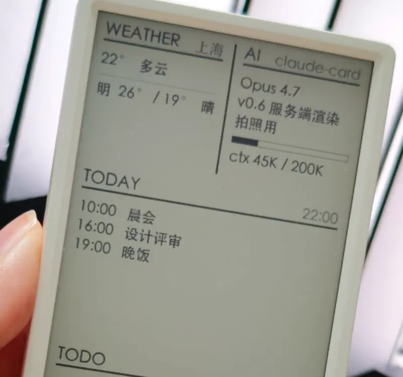
AI Desk Card
A secondary e-ink desk display designed for AI Agents like Claude Code and Codex, utilizing the M5Paper V1.1 hardware. The project features a Python-based daemon for server-side rendering and an ESP32 firmware that supports Wi-Fi, BLE, and USB communication.
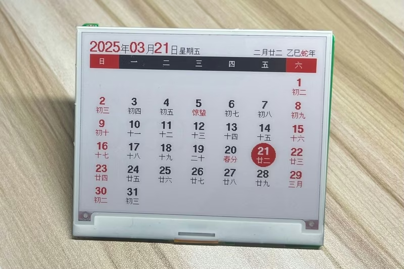
EPD-nRF5: E-Paper Display Calendar and Photo Frame
An embedded firmware for nRF51 and nRF52 microcontrollers designed to drive e-paper displays for calendar and digital photo frame applications. It features Bluetooth image transmission, Chinese lunar calendar support, and a Web Bluetooth interface for cross-platform configuration.
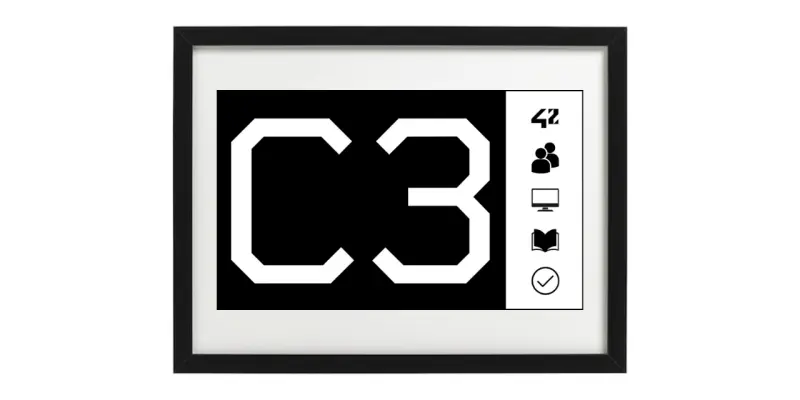
42 Smart Cluster Sign
An autonomous IoT information display for 42 school clusters using an ESP32-C3 and a 7.5-inch e-paper screen. It synchronizes with the 42 Intra API to display exam schedules, supports remote management via Telegram, and features OTA updates.
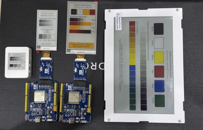
ESP E-Paper Component
A flexible e-paper display driver for the ESP-IDF framework featuring LVGL 9 integration. It supports a wide range of panels including black/white, 4-color BWRY, and 6-color displays with advanced features like Floyd-Steinberg dithering and partial refresh. Designed for low-power IoT devices, electronic shelf labels, and photo frames on ESP32 series microcontrollers.
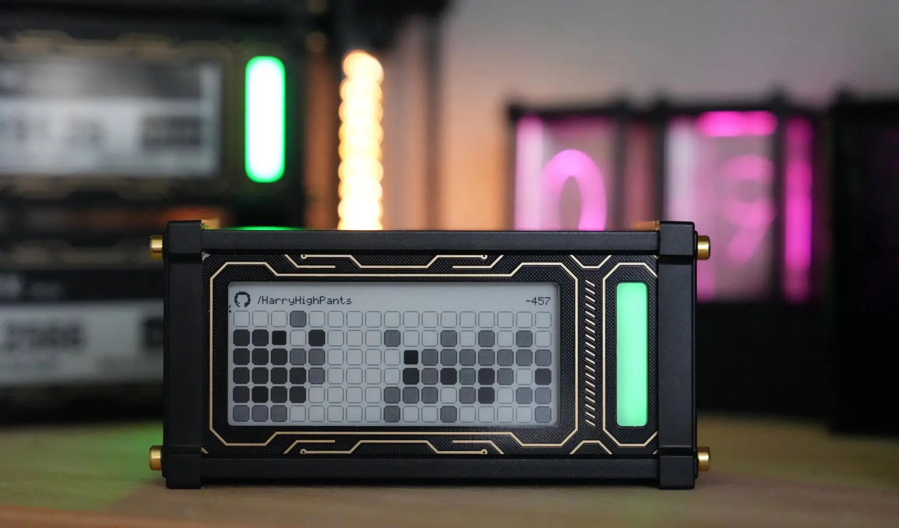
Git Contributions E-Ink Display
An ESP32-based wireless e-ink display designed to track and showcase GitHub contribution streaks. Utilizing the Lilygo T5 development board, the project features ultra-low power consumption for months of battery life and a captive portal for easy WiFi configuration.