DIY Weather Clock Firmware
This project is an alternative open-source firmware for the popular ESP8266-based DIY Weather Clock kits. It features an integrated web configuration portal, NTP time synchronization with DST support, and weather data integration from wttr.in and Netatmo stations.
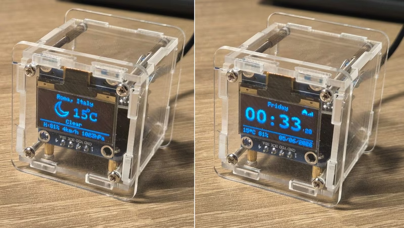
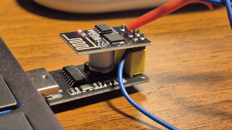
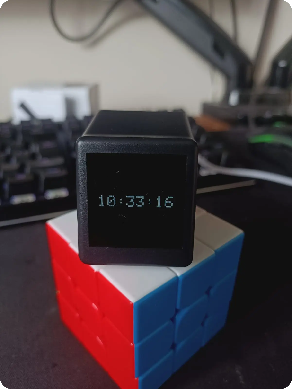
This repository provides an alternative firmware for the DIY Weather Clock WiFi kit, a common electronics project found on retailers like Amazon and AliExpress. The hardware typically consists of a plexiglass structure housing an ESP-01S module (ESP8266 MCU), a 0.96” Adafruit-compatible OLED display (128x64 px), and an interface PCB.
Motivation for Alternative Firmware
The stock firmware included with these kits often requires registration on external websites, offering limited control over data privacy and device behavior. This project originated as a fork of existing open-source efforts, heavily cleaned and modified to improve robustness. Key improvements include the removal of external service dependencies, support for both metric and imperial units, and the implementation of automatic daylight-saving time (DST) rules using proper timezone handling rather than fixed offsets.
System Architecture and Operation
Upon its first boot, the firmware searches the EEPROM for a specific magic signature. If the signature is absent, the device enters Access Point (AP) mode and displays connection instructions on the OLED. Users can then connect to the AP to access a web-based configuration portal. This portal allows for the setup of Wi-Fi credentials (including a network scanner), city selection for weather data, timezone configuration, and display preferences like seconds display or unit systems.
Once configured, the device connects to the local Wi-Fi and begins its normal operational cycle:
- Time Synchronization: Time is retrieved via NTP pool servers.
- Weather Data: The device fetches weather information from wttr.in every 15 minutes.
- Display Logic: The screen toggles between a clock view and a weather view every 15 seconds. If weather data is unavailable, the device defaults to the clock view.
- Remote Management: A web portal remains available at the device’s IP address for re-configuration, remote serial logging (via a RAM buffer), and firmware updates.
Netatmo Integration
For users who own a Netatmo Weather Station, the firmware supports displaying local sensor data. While the general weather condition icons and sun times are still sourced from wttr.in, the clock can overlay precise outdoor temperature, humidity, and pressure readings from the user’s own station. This integration requires a one-time OAuth2 setup through the Netatmo developer portal to obtain a refresh token, which the clock then manages automatically to maintain access.
Hardware and Installation Requirements
Compiling and installing the firmware requires the Arduino IDE or PlatformIO. The firmware is optimized for the ESP-01S with 1MB of flash memory.
Critical Hardware Considerations
- Voltage: A 3.3V FTDI adapter or dedicated ESP-01 USB adapter must be used; 5V will damage the MCU.
- Flash Mode: GPIO0 must be tied to GND during power-up to enter UART flashing mode.
- Pull-up Resistor: Some non-kit ESP-01 modules lack a pull-up on GPIO2, which may require a manual 12 kΩ resistor between GPIO2 and 3.3V for stable operation.
Software Configuration
When using the Arduino IDE, it is mandatory to select the “1MB (FS:none OTA:~502KB)” flash layout. This configuration is necessary because the firmware does not use a filesystem and requires the reclaimed space to accommodate Over-the-Air (OTA) updates. PlatformIO users will find this automatically configured via the platformio.ini file.
Maintenance and Updates
After the initial serial flash, the device supports OTA updates. Users can build a new binary and upload it directly through the /update endpoint on the device’s web server. This preserves the saved configuration in EEPROM and eliminates the need for physical cable connections for future firmware iterations.
Related Projects
Desk Weather Clock (GeekMagic-S3)
An ESP32-S3 firmware for the GeekMagic-S3 hardware that displays time, date, and weather data. It leverages FreeRTOS and LVGL to provide a responsive 240x240 UI, features a web configuration interface, and supports remote image and text notifications via HTTP endpoints.
EleksTube IPS Custom Firmware
This project provides a feature-rich custom firmware for ESP32-based EleksTube IPS digital clocks, enabling internet time synchronization and weather updates. It utilizes the TFT_eSPI library for high-quality display management and LittleFS for asset storage, while offering a web-based configuration portal and MQTT integration for smart home ecosystems.

ESP32-WeatherStationRTC
This ESP32-based desk clock provides real-time monitoring of temperature, atmospheric pressure, and humidity using the BME280 sensor and a DS3231 RTC. The system features an auto-dimming MAX7219 LED matrix display, WiFi-based NTP time synchronization, and a built-in web server for configuration, all developed using the Arduino framework and SPIFFS for data management.
Geek Magic Firmware
A custom ESP8266 firmware for Geek Magic smart clock clones featuring NTP synchronization, Pomodoro timers, and a web-based configuration dashboard. It utilizes the TFT_eSPI library for display management and LittleFS for asset storage. The project also includes a Linux-based companion server for forwarding system notifications to the device display.
ESPTimeCast
A WiFi-connected LED matrix clock and weather display built for ESP8266 and ESP32 microcontrollers. It utilizes the MAX7219 driver to display real-time NTP clock data and live weather updates from OpenWeatherMap, all configurable via a built-in web interface.