USB PD Tester
A monitoring and triggering device for USB Power Delivery built around the CH32X035 RISC-V microcontroller. It identifies power supply capabilities via PDOs, displays them on an OLED screen, and allows users to select specific voltages for output via a screw terminal. The project leverages the integrated USB PD PHY of the CH32X035 for a compact and low-cost hardware implementation.
The USB PD Tester is a specialized monitoring and triggering device designed to interface with USB Power Delivery systems. It provides a practical way to test various USB Type-C PD power supplies and cables by acting as a sink device. Beyond simple testing, the device functions as a versatile variable power supply, enabling users to select fixed or programmable voltages to power external projects via a screw terminal.
At the heart of the device is the CH32X035, an inexpensive RISC-V microcontroller that features integrated hardware support for USB 2.0 and USB PD 2.0/3.0. This integration significantly simplifies the hardware design by handling the complex signaling required for Power Delivery negotiation within the silicon itself.
Understanding USB Power Delivery
USB Power Delivery (USB PD) facilitates high-speed charging and power exchange through a negotiation process between a source (the power supply) and a sink (the tester). Communication occurs over the Configuration Channel (CC) lines. The devices exchange Power Delivery Objects (PDOs), which are data structures containing information about supported voltage and current levels.
This tester supports both standard fixed PDOs and Programmable Power Supply (PPS) features. PPS allows for dynamic, fine-grained adjustments of voltage and current during operation, offering much greater flexibility than traditional fixed-voltage increments. By acting as the sink, the tester requests specific power profiles from the source to verify its capabilities and output the desired power.
Hardware Architecture
The circuit is designed to be simple yet robust, utilizing the internal peripherals of the CH32X035F7P6. This 32-bit RISC-V microcontroller operates at frequencies up to 48MHz and includes 48KB of flash and 20KB of SRAM. Its built-in USB PD PHY is the critical component that manages the CC1 and CC2 communication lines.
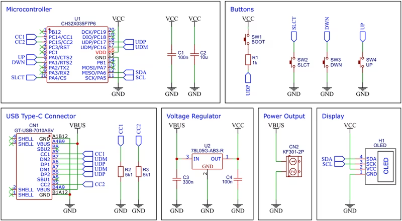
To provide a stable 5V supply for the internal logic and the display, the board uses a 78L05 voltage regulator. This regulator can handle input voltages up to 30V, which is essential since USB PD can negotiate voltages up to 20V or more. Visual feedback is provided by a standard SSD1306 0.96-inch OLED module connected via I2C, displaying the available power profiles and the currently selected output.
Firmware and Development
The firmware is developed using the RISC-V GCC toolchain and the Newlib C library. It can be compiled and flashed using several methods, including a standard Makefile or the PlatformIO ecosystem. The CH32X035 includes an embedded USB bootloader, allowing for firmware updates without the need for an external programmer. Users can trigger the bootloader by holding a dedicated BOOT button during power-up, making it accessible for rapid prototyping and updates.
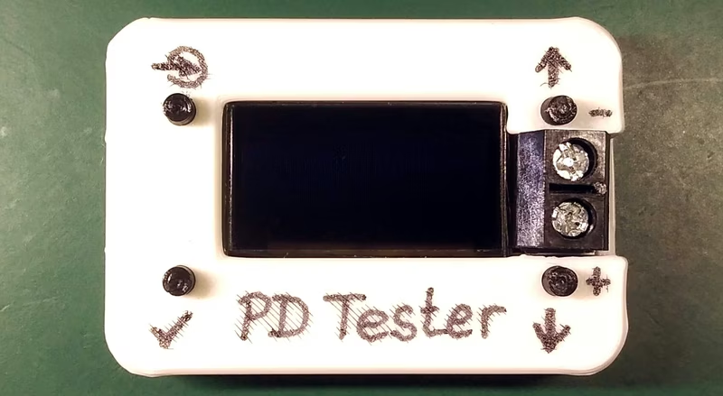
Construction and Assembly
The physical build involves a custom PCB and a 3D-printed enclosure. The assembly process follows a standard flow: soldering surface-mount components, attaching the OLED module flush to the board, and securing the assembly into the housing. Button extensions allow the user to interact with the internal tactile switches through the top of the case. A screw terminal is used for the final output, providing a secure connection for powering external loads.
Operation and Use
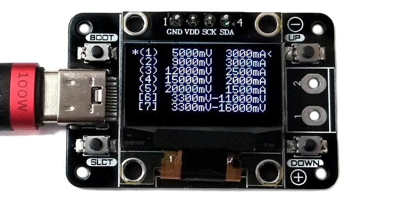
Operating the device is straightforward. Once connected to a USB-C power supply, the OLED immediately populates with the list of available PDOs offered by the source.
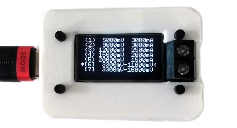
Navigation is handled via UP and DOWN buttons, with a selection indicator showing the currently highlighted profile. For PPS-capable profiles, the user can adjust the output voltage in precise 20mV steps. Once the desired profile is selected, pressing the SLCT button triggers the negotiation. An asterisk indicates the active PDO, and the negotiated voltage becomes available at the screw terminals for the connected application.