USB PD Adapter
A compact variable power supply that utilizes the PPS feature of USB Type-C PD supplies to provide adjustable output voltages and currents. It is powered by the CH32X035 RISC-V microcontroller and includes an INA219 sensor for real-time power monitoring and an OLED display.
The USB PD Adapter is a compact variable power supply designed to turn any USB Type-C PD power supply with Programmable Power Supply (PPS) capabilities into a versatile laboratory-style power source. By negotiating with the input supply, the adapter can provide various selectable voltages and high currents for powering external projects. Key parameters, including voltage, current, power, and energy consumption, are displayed in real-time on an integrated OLED screen.
Hardware Architecture
At the heart of the device is the CH32X035F7P6, a highly cost-effective 32-bit RISC-V microcontroller. This MCU utilizes the QingKe V4C core and is specifically chosen for its built-in USB PD PHY, which supports both source and sink capabilities. The microcontroller handles power negotiation protocols, manages the user interface, and processes data from the sensors. Operating at frequencies up to 48MHz, it includes 48KB of flash and 20KB of SRAM, making it well-suited for this application.
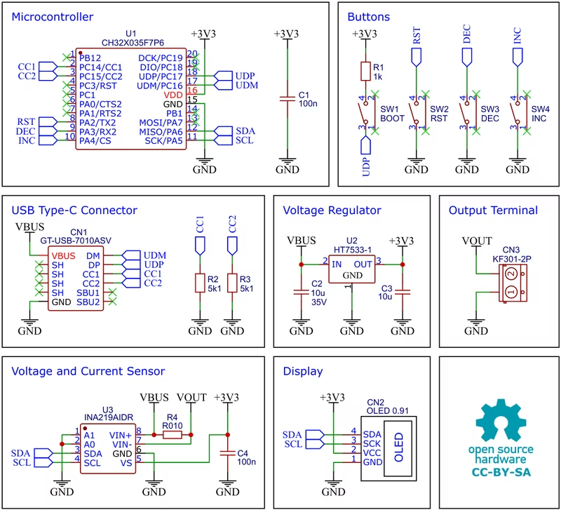
To ensure accurate power measurement, the design incorporates the INA219 current shunt and power monitor. This IC communicates with the MCU via I²C and monitors both the bus supply voltage and the voltage drop across a 10mΩ shunt resistor. This low-resistance shunt minimizes circuit interference while providing a measurement resolution of 1mA. Power for the internal logic is provided by an HT7533-1 voltage regulator, a CMOS-based high-current LDO that supplies a stable 3.3V even with input voltages up to 30V.
User Interface and Assembly
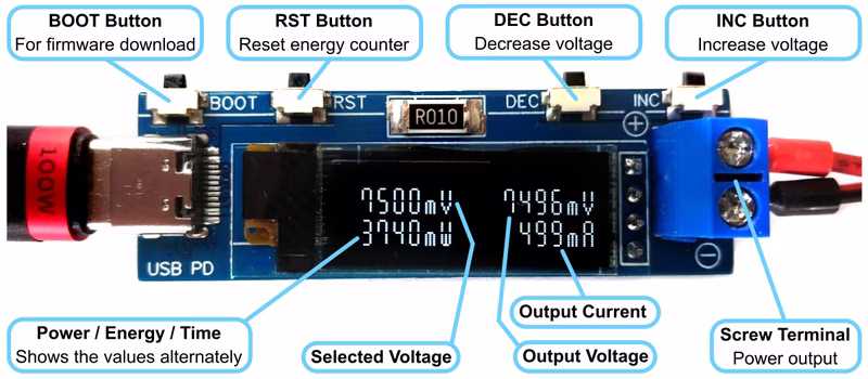
The user interface is designed for simplicity and clarity. It features a 0.91-inch SSD1306 I²C OLED display with a resolution of 128x32 pixels. Users interact with the device through three tactile buttons—Increment (INC), Decrement (DEC), and Reset (RST).
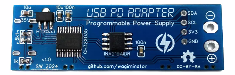
Construction involves a standard PCB assembly process. The OLED module is soldered flush onto the board after removing the plastic part from its pin header and trimming the pins. The output is provided via a standard screw terminal for easy connection to various projects.
Software and Firmware Development
The firmware is developed for the RISC-V architecture and can be compiled using several methods. For Linux users, a standard GNU RISC-V embedded toolchain paired with a Makefile is provided. Alternatively, the project supports PlatformIO for a more integrated development experience.
Flashing the firmware is handled through the CH32X035’s embedded USB bootloader. This requires putting the device into bootloader mode by holding the BOOT button while connecting it to a PC. Once in this mode, the firmware can be uploaded using tools like chprog or the WCHISPTool for Windows.
Operating Instructions
Using the adapter is straightforward. Once connected to a USB Type-C PD power supply, the user can adjust the output voltage in 20mV increments using the INC and DEC buttons. The RST button is dedicated to clearing the energy counter, allowing for precise tracking of power consumption over time for a specific test run.