RP2040/RP2350 ADC Non-linearity Correction
This project provides software-based tools and algorithms to correct the ADC non-linearity issues in RP2040 and RP2350 microcontrollers, specifically addressing the RP2040-E11 errata. It includes measurement firmware, Python scripts for data analysis, and general-purpose or device-specific calibration code for C++ and Python environments.
The primary objective of this project is to improve the non-linearity of the Analog-to-Digital Converter (ADC) in the RP2040 microcontroller. This non-linearity is a documented hardware issue known as errata RP2040-E11. While the hardware itself cannot be altered to restore lost information, software-based correction can significantly improve linearity. The project has also been expanded to support the newer RP2350 microcontroller.
RP2040 and RP2350 ADC Measurement
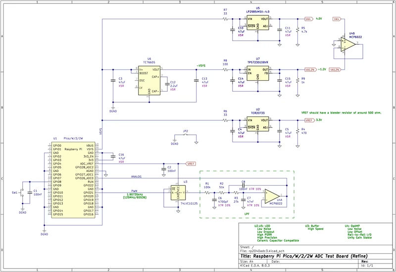
To understand the extent of the non-linearity, the project utilizes a specialized measurement setup. Data is gathered using a Python-based measurement script paired with custom firmware and a dedicated test circuit. The board design files and schematics are provided to ensure reproducible results across different hardware.
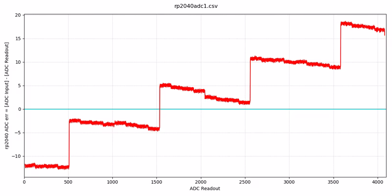
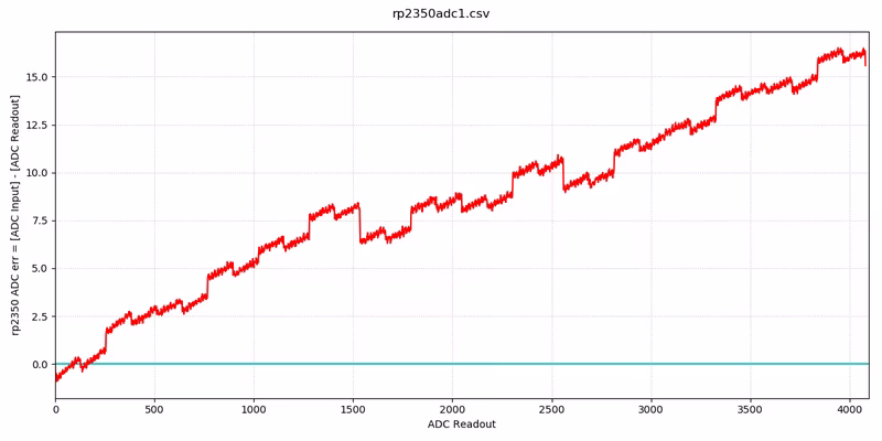
Measurement results from actual Raspberry Pi Pico, Pico W, Pico 2, and Pico 2W devices reveal significant ADC errors. In these measurements, the Y-axis represents the ADC error while the X-axis shows the ADC readout.
RP2040 ADC Non-linearity
In the RP2040, enormous discontinuities are observed at specific intervals: 512, 1536, 2560, and 3584. These spikes in error contribute to the poor performance described in the official errata.
RP2350 ADC Non-linearity
While the RP2350 shows marked improvement over its predecessor, it is not perfectly linear. Some non-linearity remains, which can still benefit from software correction to achieve higher precision in analog measurements.
General-Purpose Correction Code
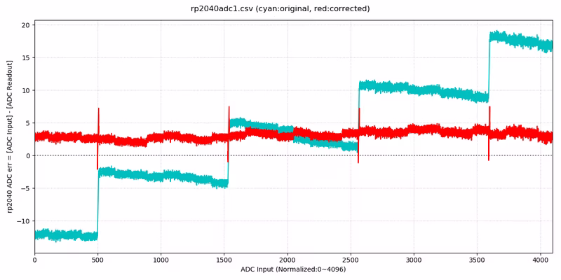
By averaging the error data from multiple devices, a general-purpose correction algorithm was developed. This code provides a standard correction that can be applied to any RP2040 or RP2350 device without needing individual calibration. The logic uses a series of conditional offsets to shift the raw ADC readout closer to the intended linear value.
Correction Results
When applying this general-purpose code, the results show a clear reduction in error. In the following graphs, the red line represents the corrected error, while the cyan line shows the original uncorrected error. Even with a generalized approach, the sharp discontinuities of the RP2040 are significantly smoothed out.
Best Calibration by Individual Code
For applications requiring the highest possible accuracy, the project supports individual device calibration. This involves generating a unique error array for a specific chip. The formula used is:
ADC_CORRECTED = ADC_READOUT + rp2040adc_err[ADC_READOUT]
Templates for implementing this in both C/C++ and Python are provided. This method ensures that the unique manufacturing variances of each specific microcontroller are accounted for.
Embedding Calibration Data in Flash
To make calibration data persistent and easy to use in production, the project includes a method to embed individual ADC calibration data in the last 4KB block of the Pico’s flash ROM. This area can be accessed as an emulated EEPROM using the Arduino-Pico core. By reading this data at startup, the firmware can apply precise, device-specific corrections in real-time.
An example implementation using the Arduino-Pico framework demonstrates how to initialize the EEPROM emulation, point to the calibration data in flash, and apply the correction offset to every analogRead() call. This creates a seamless experience where the hardware appears more linear to the application software than it is natively.
Related Projects
pico_fft: FFT Library for Raspberry Pi Pico
A lightweight and efficient wrapper for the KISS FFT library, specifically designed for the Raspberry Pi Pico (RP2040). It provides high-level functions for capturing analog signals via ADC and DMA, processing them into frequency bins, and performing real-time signal analysis.