Rotary Encoder with I²C Interface
This project implements an I2C-based interface for rotary encoders using the low-cost CH32V003 RISC-V microcontroller. It offloads debouncing and interrupt handling from the main controller and supports daisy-chaining multiple encoders via configurable I2C addresses.
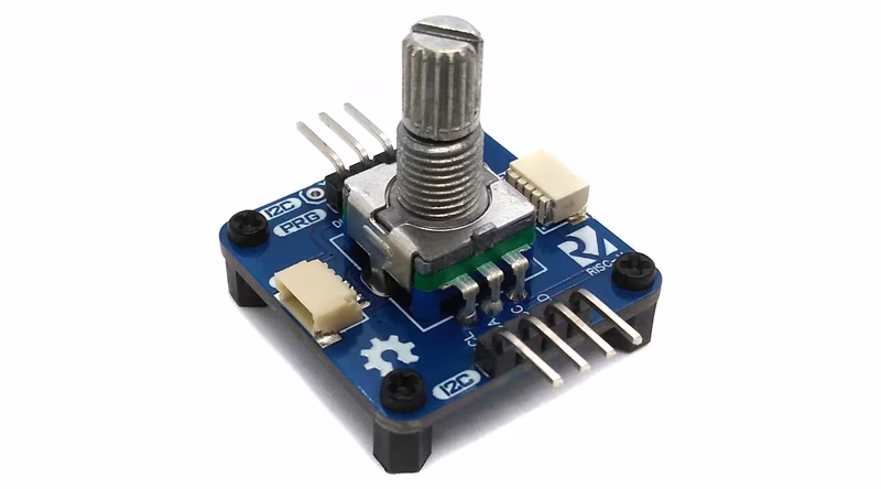
Rotary encoders are a staple in user interface design, but managing them directly often requires several GPIO pins, external interrupts, and robust software debouncing logic. This project provides a hardware and firmware solution that allows a rotary encoder to be controlled entirely over an I2C interface. By utilizing a dedicated CH32V003 microcontroller, the device handles all low-level encoder logic and presents the data through a simple register-based interface. This design also supports daisy-chaining multiple encoders by assigning unique I2C addresses to each unit, operating within a wide voltage range of 2.7V to 5.5V.
Hardware Design
The heart of the device is the CH32V003, an industrial-grade 32-bit RISC-V microcontroller. This MCU utilizes the QingKe RISC-V2A core, supporting the RV32EC instruction set with a 48MHz system frequency. Despite its small package and low cost, it includes 16KB of flash, 2KB of SRAM, and essential communication interfaces like I2C, USART, and SPI.
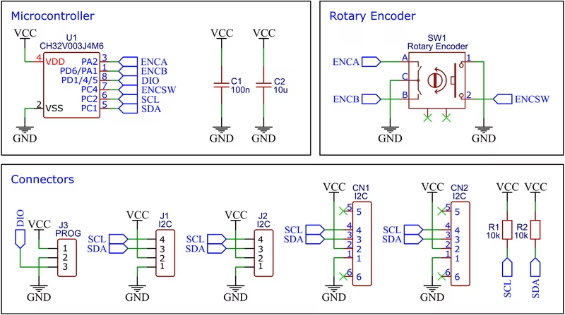
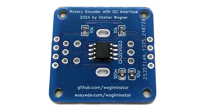
To build the hardware, users can utilize the provided Gerber files for PCB manufacturing. Once the board is fabricated, components are soldered following the Bill of Materials (BOM) and schematic. The device is powered directly through the I2C connection, making it a compact addition to existing systems.
Firmware and Programming
Programming the CH32V003 requires a specialized device such as the WCH-LinkE, which uses a proprietary single-wire serial debug interface (SDI). The firmware can be compiled and uploaded through several different workflows depending on the user’s operating system and preference.
For Linux users, a standard Makefile is provided which utilizes the RISC-V GCC toolchain and rvprog for flashing. Alternatively, the project is compatible with PlatformIO, leveraging the platform-ch32v community platform for a more integrated development experience. For those who prefer not to compile from source, pre-compiled binaries are available and can be uploaded using tools like WCH-LinkUtility or minichlink.
Operating Instructions
The device functions by exposing six internal registers that can be read or written via I2C. These registers handle the 16-bit encoder wheel value, the 8-bit switch state, and configuration flags for behavior like value looping and step size.
When accessing the device, registers are transferred in a fixed sequence:
- Encoder wheel value: A 16-bit signed integer.
- Encoder switch state: 0 for released, 1 for pressed.
- Loop flag: Determines if the value should wrap around when reaching limits.
- Minimum value: The lower bound for the encoder value.
- Maximum value: The upper bound for the encoder value.
- Step size: The increment/decrement value per detent.
Integration with other microcontrollers is straightforward. For example, using the Arduino Wire library, a developer can set the encoder parameters and read the current value with just a few lines of code:
void loop() {
  // Read encoder wheel value
  Wire.requestFrom(encoder_addr, 2);
  value = ((uint16_t)Wire.read() | ((uint16_t)Wire.read() << 8));

  // Read switch state
  Wire.requestFrom(encoder_addr, 3);
  Wire.read(); Wire.read(); // Skip value bytes
  pressed = Wire.read();
}
This abstraction allows the main application processor to focus on high-level logic while the CH32V003 ensures no encoder pulses are missed due to processing delays.