Retrofit Electronic Clock with Raspberry Pi Pico W
A hardware retrofit project that replaces a defunct TG1508 controller in a digital clock with a Raspberry Pi Pico W. It features Wi-Fi time synchronization via NTP, dual-core firmware for display management and networking, and a complete reverse-engineered schematic created in KiCad.
Retrofitting a Classic Digital Clock with Raspberry Pi Pico W
This project demonstrates a creative approach to repairing and modernizing a broken electronic clock/calendar. By replacing a proprietary, defunct controller with a Raspberry Pi Pico W, the project transforms a simple digital clock into a high-precision, Wi-Fi-connected NTP timepiece.
The Hardware Challenge
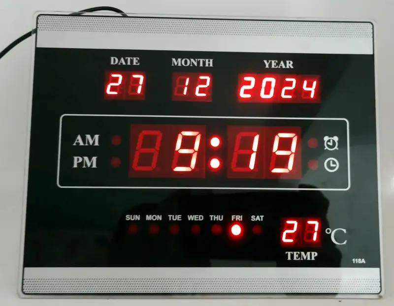
The project began with a non-functional digital clock purchased from a recycling center. Troubleshooting revealed that the original TG1508 controller was damaged. Rather than searching for an obsolete replacement part, the author chose to integrate a Raspberry Pi Pico W, which shares a similar physical footprint and provides modern connectivity.
To integrate the new microcontroller, the author performed extensive reverse engineering on the original PCB. This process involved:
- Photographing the solder side of the board.
- Importing and scaling the image within KiCad to match the physical layout.
- Tracing the existing connections to create a complete electrical schematic.
- Mapping the 12 seven-segment displays (day, month, year, hour, minute, and temperature) and various status LEDs.
The final hardware design includes seven 100-ohm current-limiting resistors for the LED segments and a modified temperature sensing circuit. The original battery holder and a large capacitor were removed to make room for the Pico W assembly. Detailed KiCad project files and schematics can be found in the hardware documentation of the repository.
Dual-Core Firmware Architecture
The firmware, developed using the Arduino framework within PlatformIO, leverages the dual-core architecture of the RP2040. This separation of concerns ensures that the user interface remains responsive while the device handles network communication.
Core 0: Networking and Timekeeping
Core 0 is dedicated to maintaining the clock’s accuracy. It handles Wi-Fi connectivity and periodically synchronizes with NTP servers. The firmware is designed for resilience, checking the connection status and attempting to reconnect if the signal is lost. Once time data is retrieved, it updates the Pico W’s internal Real-Time Clock (RTC) every minute.
Core 1: Display and LED Control
Core 1 manages the visual output. The clock features a complex array of 12 seven-segment displays and 13 individual LEDs. To drive these, the firmware uses a multiplexing technique where each common pin is activated for 1ms. This high refresh rate ensures a flicker-free display through persistence of vision. The firmware documentation provides further insights into the multiplexing logic and core synchronization.
Temperature Measurement
One of the technical hurdles encountered was the original temperature sensor’s multiplexing, which caused flickering in the new firmware. To resolve this, the thermistor was desoldered from the original circuit and connected directly to one of the Pico W’s Analog-to-Digital Converter (ADC) pins with a 10k ohm pull-down resistor.
The firmware calculates the temperature using the Steinhart-Hart equation. To ensure accuracy, the result was calibrated against a professional multimeter with a thermocouple, resulting in satisfactory real-world performance.
Conclusion
By combining reverse engineering with modern embedded development, this project successfully breathes new life into discarded hardware. It serves as an excellent reference for anyone looking to retrofit legacy electronics with modern IoT capabilities, demonstrating how to bridge the gap between old-school LED multiplexing and modern Wi-Fi connectivity.