Pico USB Blaster
This firmware transforms Raspberry Pi Pico or other RP2040/RP2350-based boards into an Altera USB-blaster compatible JTAG/AS/PS programmer. It leverages the tinyUSB stack for USB communication, making it compatible with Intel Quartus, OpenOCD, and other standard FPGA programming tools. The project supports various programming modes and includes optional support for level shifters and RGB status LEDs.
Pico USB Blaster is a firmware solution designed to turn a Raspberry Pi Pico, or any board based on the RP2040 or RP2350 microcontrollers, into a fully functional Altera USB-blaster / Intel FPGA Download Cable compatible programmer. This tool allows developers to program and debug FPGAs using standard tools like Quartus and OpenOCD without needing the official proprietary hardware.
The project is built specifically to rely on the tinyUSB stack. This design choice ensures that the firmware is not only lightweight but also easily portable to any other hardware platforms capable of running tinyUSB.
Getting Started and Hardware Requirements
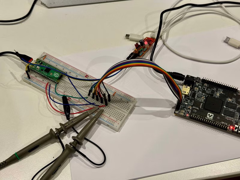
To build a Pico USB Blaster, you primarily need a Raspberry Pi Pico, Pico 2, or a similar RP2040/RP2350 board. If you intend to operate with target devices that do not use 3.3V logic, a fast level shifter is required. It is important to select a level shifter capable of handling the 1k TCK pulldown often found on Intel JTAG headers. While the TXS0108E is a common choice, users should be aware that it may struggle with signal integrity under specific pulldown loads, potentially dropping TCK voltage levels.
Flashing the device is straightforward. You can either download a pre-built UF2 release or compile the source using the standard CMake workflow provided in the repository. Once compiled, the resulting binary is loaded onto the Pico by connecting it via USB while holding the BOOTSEL button.
Pinout and Hardware Mapping
The firmware uses a logical sequential mapping for data pins to keep the wiring simple. The default configuration centers around GP11 for the TCK/DCLK signal, with other pins mapped as follows:
- GP11: TCK / DCLK
- GP12: TMS / nCONFIG
- GP13: nCE
- GP14: nCS
- GP15: TDI / ASDI / DATA0
- GP16: TDO / CONF_DONE
- GP17: DATAOUT / nSTATUS
Additionally, GP0 provides a debug UART TX line, while GP25 (the onboard LED) serves as an activity indicator and output enable signal.
Driver Compatibility and USB Architecture
The device is designed to be a drop-in replacement for the original Altera hardware. It replicates the USB descriptor structure of the official USB-Blaster, including the Vendor ID (0x09fb) and Product ID (0x6001). This allows users to follow the standard ‘Installing the Intel FPGA Download Cable Driver’ instructions from Intel’s website.
While the VID and PID are fixed for compatibility, the board provides a unique serial number via the tinyUSB BSP, ensuring that multiple adapters can be connected to the same host system without conflicts. The device operates as a Vendor Specific Class device using bulk endpoints for high-speed data transfer.
Advanced Implementations and Enclosures
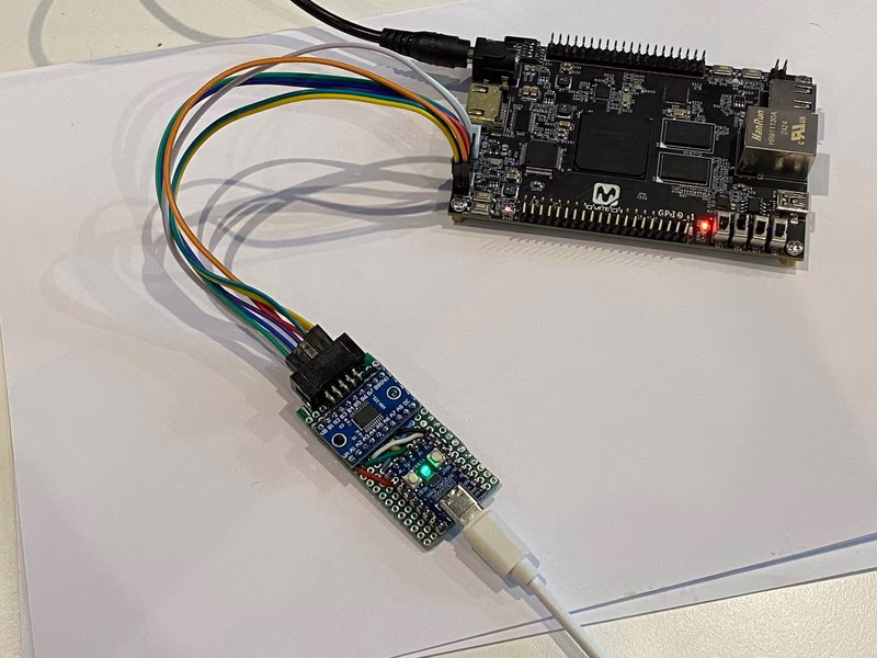
For those looking for a more polished tool, the project supports compact form factors like the RP2040-zero board. This specific setup is ideal for creating a small, portable programmer. The firmware includes support for onboard WS2812 RGB LEDs to provide visual status feedback, using a dedicated PIO (Programmable I/O) state machine for precise timing.
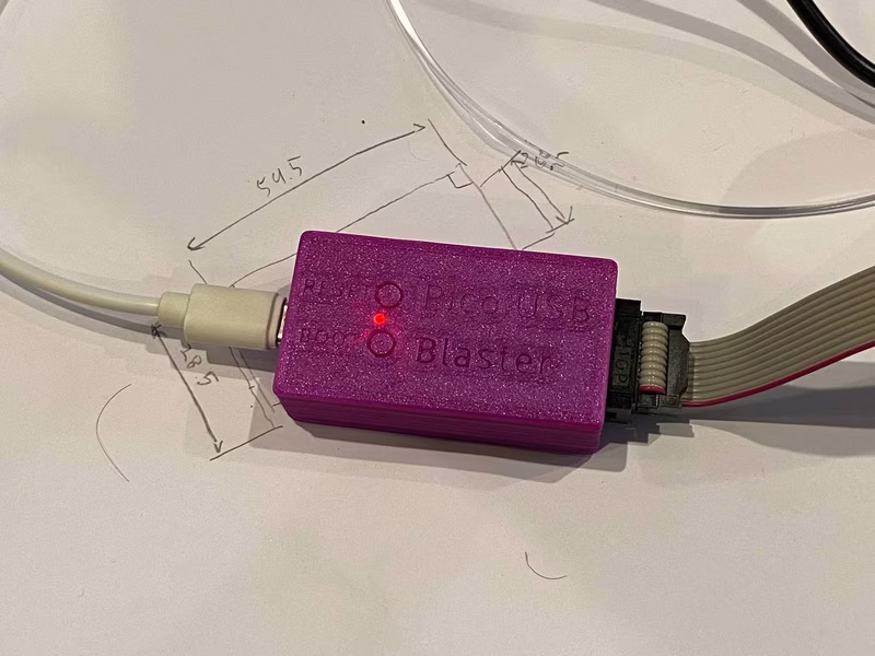
To complete the project, a 3D-printable enclosure is available, providing a professional finish and protecting the electronics. The enclosure files include STLs and Fusion 360 source files for further customization.
Technical Lineage
The Pico USB Blaster builds upon several decades of community knowledge. The protocol implementation and specs were derived from existing projects like Teensy_Blaster and usbd-blaster, as well as historical forum documentation. The high-performance LED control is handled via PIO code adapted from the Raspberry Pi pico-examples repository.