Hexapod
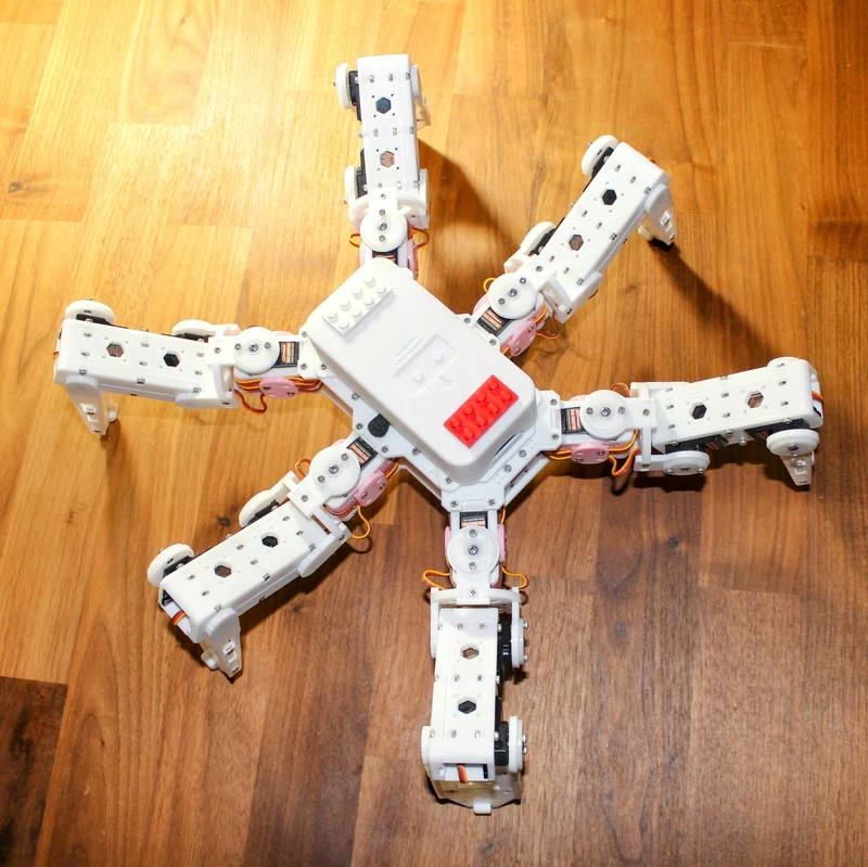
A 3D-printed, 18-servo hexapod robot platform designed for agility and flexibility, supporting both ESP32 and Raspberry Pi Pico controllers. The project features WiFi-enabled remote control via UDP, Over-the-Air (OTA) firmware updates, and a modular mechanical design optimized for 3D printing.
Introduction
This project features an agile, 3D-printed hexapod robot designed for high performance and flexibility. It supports two major microcontroller platforms: the Raspberry Pi Pico and the ESP32. Unlike earlier iterations that relied on weaker components, this version is optimized for 21G servos, which provide the strength and speed necessary for smooth, complex movement patterns.
Key features of the system include a robust and durable 3D-printed structure, WiFi-enabled remote control, and support for Over-the-Air (OTA) updates, allowing for easy firmware maintenance without needing a physical connection.
Electronics and Control
The robot’s brain can be either an ESP32 or a Raspberry Pi Pico W/2W, depending on the user’s preference for processing power and ecosystem. The control system manages 18 individual 21G servos (such as DS Power or Miuzei models) to actuate the six legs. Power is provided by a pair of 18650 batteries, ensuring sufficient current for the high-torque demands of hexapod locomotion.
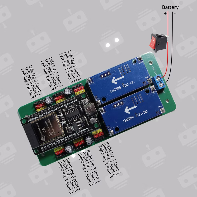
Communication is handled over WiFi using UDP packets, providing a low-latency interface for remote movement commands. The electronics are integrated using custom controller boards designed specifically for either the ESP32 or the Pico form factors.
Mechanical Assembly
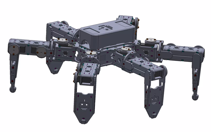
The hexapod’s body and limbs are entirely 3D-printed, designed to be printed without supports. The assembly is modular, consisting of several key sub-assemblies:
- Body: A central chassis that houses the controller board, battery holder, and the primary leg servos.
- Joints: Six pairs of mirrored joints that connect the body to the legs.
- Legs and Feet: Six legs equipped with ground-contact tips to provide stability and grip during movement.
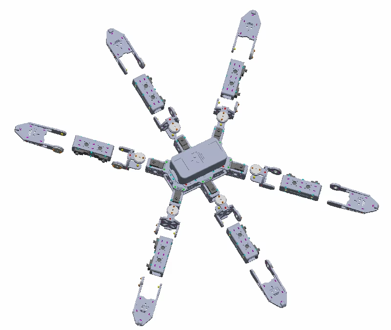
In addition to the printed parts, the build requires standard hardware including M2 screws and nuts, M4 pins, and MR74-2RS bearings to ensure smooth rotation at the joints.
Software Architecture
The firmware is provided for both ESP32 and Raspberry Pi Pico platforms using the Arduino framework.
- ESP32 Implementation: Utilizes the Adafruit PWM Servo Driver library for I2C-based motor control and standard networking libraries for WiFi and OTA updates.
- Pico Implementation: Uses a custom
PicoPWM.hlibrary for hardware motor control andAsyncUDP.hfor network communication.
Both implementations share a common configuration structure. The motion.h file contains automatically generated motion look-up tables (LUTs) that define the walking gaits, while config.h allows users to define servo pins and installation offsets.
Calibration
Proper movement requires precise calibration of the leg joints. The initial position for all servos should be 90 degrees, resulting in specific leg orientations as defined in the project documentation.
Because 3D printing and manual assembly can introduce small physical variances, the software includes a mechanism to correct installation offsets. Users can adjust the left_offset_ticks and right_offset_ticks arrays in the configuration header to ensure the robot stands and walks symmetrically.