FlyBrain Robot Bridge
FlyBrain Robot Bridge connects visual motion sensing and Drosophila-inspired neural simulations to physical robots over UDP. It features a Python-based processing pipeline that decodes synthetic or camera inputs into differential drive commands, paired with an ESP32-based firmware scaffold for platforms like the M5Stack Atom Matrix.
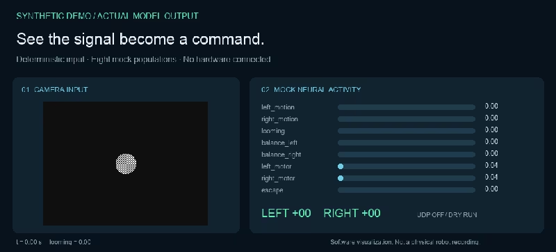
Bridging Connectomics and Robotics
FlyBrain Robot Bridge explores an experimental interface connecting insect-inspired neural network simulations with physical robotic hardware. Taking visual motion cues and IMU orientation data, the bridge passes real-time sensor streams into a neural backend, decodes the resulting activation patterns, and transmits motor commands to a robot over UDP.
While complete digital emulation of biological brains remains an open scientific challenge, this proof of concept establishes the computational and communication pipeline required for embodied neural experimentation.
Architecture and Signal Pipeline
The bridge operates on a closed-loop flow between a host machine executing sensory-neural processing and a microcontroller managing low-level actuation:
Camera / Synthetic Frames → VisionEncoder → BrainBackend → MotorDecoder → UDP → Robot
Robot IMU → UDP Telemetry → BrainBackend
At the core of the demonstrator is an eight-group leaky activity model representing engineered signals rather than biological neurons:
- Visual signals:
left_motion,right_motion, andlooming(optical-flow expansion heuristics) - Proprioception:
balance_leftandbalance_rightdriven by gyro yaw feedback - Motor groups:
left_motor,right_motor, andescape(which triggers reverse motion upon rapid looming cues)
The software pipeline performs optical-flow estimation across both image halves, smooths and bounds motor output values, and validates incoming and outgoing UDP packets with watchdog timeouts.
Embedded Firmware Scaffold
On the hardware side, the project targets small ESP32 platforms such as the M5Stack Atom Matrix. The accompanying Arduino firmware (atom_matrix_robot.ino) sets up a lightweight control loop:
- Joins local Wi-Fi and listens on a dedicated UDP socket for JSON-formatted motor commands.
- Packages onboard IMU readings and status telemetry into JSON datagrams broadcast back to the host.
- Implements a hardware-side safety watchdog that zeros out motor outputs if fresh UDP packets stop arriving within 500 ms.
To prevent unexpected movement during development, the firmware scaffold is intentionally disarmed until board-specific servo PWM and IMU drivers are calibrated for the target chassis (such as a Strandbeest walking robot mechanism).
Local Testing and Synthetic Demos
A key strength of the bridge is its zero-hardware test mode. Developers can validate the complete signal chain locally without physical robots, cameras, or external network access:
# Install in development mode
pip install -e ".[dev]"

# Run deterministic synthetic signal-flow demo
python -m flybrain_robot.main --backend mock --synthetic --steps 90 --dry-run
In synthetic mode, the runtime generates deterministic camera frames, simulates IMU oscillations, updates neural activity states, and prints decoded motor commands directly to the terminal.
Future Directions
Current integration targets include loading partial MaleCNS connectome datasets, mapping visual neural populations to motor populations, and implementing hardware-in-the-loop tests with live servo outputs.