Custom STM32-based PCBs
A comprehensive guide and project for designing custom STM32H573-based PCBs, moving from schematic capture in KiCad to firmware development with STM32CubeIDE. It details essential hardware requirements like power regulation, external oscillators for USB, and 4-layer PCB stackups for signal integrity.
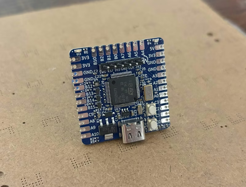
Transitioning from off-the-shelf development boards like an Arduino or ESP32 to custom-designed PCBs is a significant milestone for any embedded systems developer. This project provides a roadmap for creating custom hardware centered around the STM32H573RIT6, a high-performance microcontroller based on the ARM Cortex-M33 architecture. By moving beyond pre-built modules, developers gain full control over form factor, power efficiency, and peripheral selection, making it possible to create production-ready devices.
The core of the project is the STM32H5 series, which offers a balance of performance and memory efficiency. Unlike older legacy chips, the H5 series provides modern features and better cost-to-performance ratios. The design process begins in KiCad, where a schematic is developed to support the MCU’s requirements. This includes a robust power supply scheme—utilizing either Low-Dropout (LDO) regulators or Switch-Mode Power Supplies (SMPS)—and a strategic array of decoupling capacitors to ensure stable operation and minimize electrical noise.
Hardware Design Considerations
One of the critical technical decisions highlighted in this project is the use of an external 8MHz crystal oscillator. While many STM32 chips include internal oscillators, an external crystal is essential for frequency-sensitive applications like USB communication. The hardware design also integrates a Serial Wire Debug (SWD) interface, utilizing SWCLK, SWDIO, and SWO pins for seamless code deployment and real-time logging. Proper resistor arrangements for the NRST and BOOT0 pins are also detailed to ensure the board can be reliably reset or placed into firmware upload modes.
When it comes to the physical PCB layout, the project emphasizes a four-layer stackup. This approach allows for dedicated ground and power planes, which are vital for signal integrity and reducing electromagnetic interference (EMI). Key layout strategies include placing critical components—such as the USB differential pairs and decoupling capacitors—as close to the MCU as possible. Wide traces are used for power paths to handle current demands, and ground pours are applied across the board to improve both thermal dissipation and electrical performance.
Firmware and Configuration
On the software side, the project utilizes the STM32Cube ecosystem. A provided configuration file allows developers to manage peripheral initialization for I2C, I3C, SPI, UART, and USB interfaces. The firmware relies on the STM32H5 HAL (Hardware Abstraction Layer) library, which abstracts low-level register manipulations into manageable API calls. This allows for rapid development while maintaining the flexibility to optimize performance where needed. The build process is managed via a standard Makefile and the GNU Arm Embedded Toolchain, targeting the Cortex-M33 architecture.
Finally, the project touches on the assembly process, advocating for the use of stencils and hotplate reflow methods. This approach is often more reliable than hand-soldering for fine-pitch QFP or QFN packages, resulting in a professional-grade finish that is ready for deployment in real-world applications. By following this lifecycle, developers can move from a concept on a breadboard to a fully functional, custom-manufactured embedded system.
Related Projects
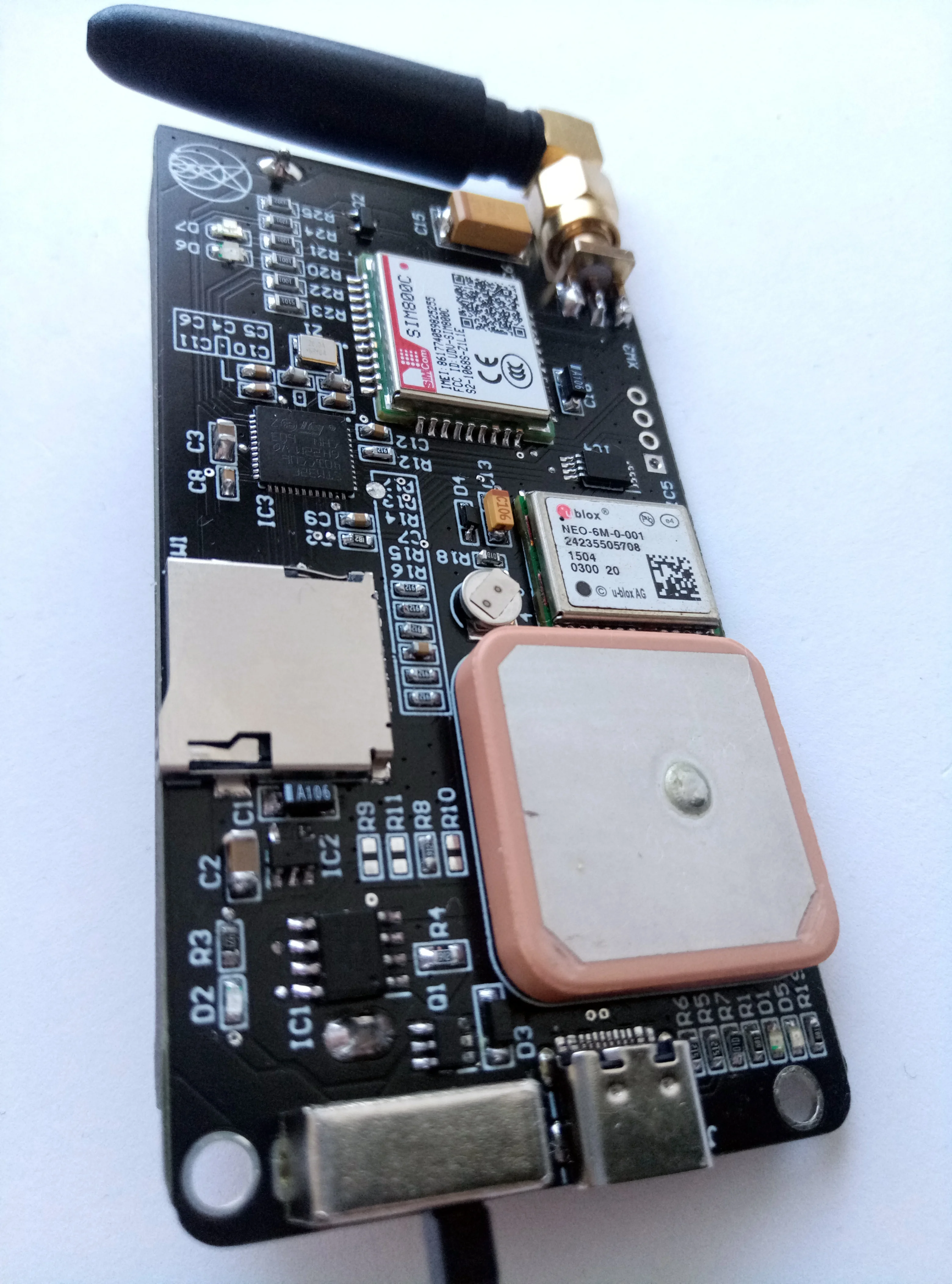
GPS-Tracker
An embedded GPS tracking system featuring custom hardware and firmware. The project includes a dedicated PCB design and software components for capturing and managing location data.