2D LIDAR Edge Detection using Raspberry Pi Pico
This project implements an edge detection system for mobile robots using a 2D LIDAR sensor and a Raspberry Pi Pico. It processes real-time scan data to calculate distances to upcoming edges or 'holes' by comparing measured values against a geometric model of the floor surface.
This project focuses on developing the logic required to calculate the distance to the next edge for a robot equipped with a 2D LIDAR sensor. Designed for applications such as table-top navigation, the system identifies drop-offs or holes in the environment to prevent the robot from falling. The implementation leverages the processing power of the Raspberry Pi Pico and interfaces with hardware using the RPLidar.h library.
Project Overview
The core objective is to refine a method for edge detection through several experimental stages. By using a 2D LIDAR sensor, the system captures environmental data, which is then processed to determine the proximity of the next geometric discontinuity. This is particularly useful for robots that need to operate on elevated surfaces where detecting the boundary of the surface is a safety requirement.
Hardware and Libraries
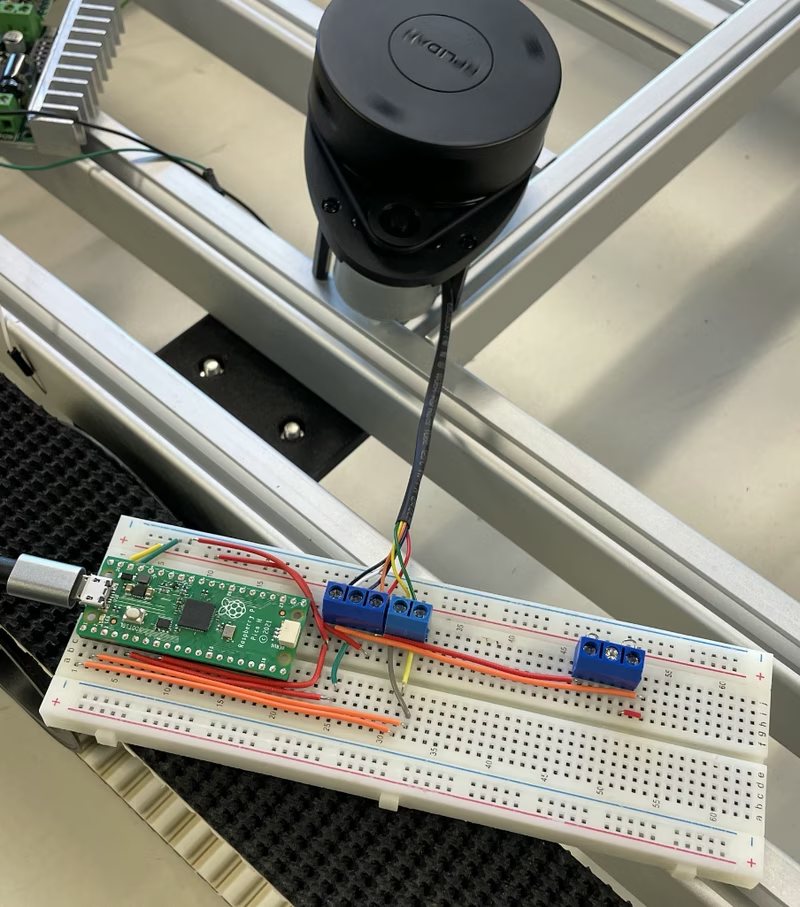
The hardware platform is the Raspberry Pi Pico, which manages communication with the LIDAR sensor. The project relies on two primary external libraries:
- RPlidar.h: Used for interfacing with the hardware, managing motor speed, and parsing data streams from the 2D LIDAR.
- Filters: Utilized for signal smoothing and data filtering to ensure more accurate distance readings.
Project Workflow
The development follows a structured workflow, moving from raw data acquisition to sophisticated filtering and edge detection logic.
Continuous Data Retrieval
The first step involves maintaining a stable and continuous data stream from the LIDAR. The firmware manages the sensor’s motor speed and scan states to capture real-time distance and angular data. This data is streamed via a serial connection for external processing or immediate analysis on the Pico.
LIDAR Hole Processor
To identify features like holes or edges, the system captures 360-degree scan data and stores it in arrays. The “Hole Processor” sorts these readings by angle to create a coherent map of the surroundings. By analyzing these arrays, the system can identify specific angular sectors where the distance readings deviate from the expected floor profile.
Edge Detection Logic
The edge detection logic is built on a geometric model. By knowing the mounting height of the sensor and the angle of the scan, the system calculates a theoretical distance to the ground. If the measured distance significantly exceeds this theoretical value, the system identifies the presence of an edge or a hole. This comparison allows the robot to distinguish between the flat surface it is driving on and a sudden drop-off.
Calculating Distance to the Next Edge
The final stage of the workflow involves calculating the precise distance to the detected edge. This is implemented in two ways:
- Non-filtered Distance: Raw calculations based on immediate sensor returns. While fast, these can be susceptible to noise in the LIDAR data.
- Filtered Distance: This approach applies a low-pass smoothing filter to the raw distance data. By reducing noise and signal jitter, the system provides a much more stable and reliable distance measurement to the upcoming edge, which is critical for the robot’s braking or turning maneuvers.
The system can also serialize this processed data into JSON format, making it easy to transmit the edge detection results to other high-level controllers or monitoring software.